|
Design of Electrode Systems for Particular Applications.
At one time a few basic pentodes or beam tetrodes were used as general-purpose power valves, but of recent years a number of different types have been designed and manufactured for such uses as scanning cathode-ray tubes, current and voltage stabilising, pulse modulation and so on. At the same time considerable improvements have been made in the more conventional types of low frequency amplifier valves. These improvements have been, in general, a reflection of the reduction in size which has taken place in almost all valve designs during the past ten years and, so far as the larger types are concerned, the reduction in cathode heating power made possible by increased use of the oxide-coated cathode.
The size of the lower-powered valves has been reduced by the use of the familiar pressed-glass base technique, and in both these and in valves of larger powers the introduction of new electrode materials and processing methods has permitted an increase in electrode loading. For example, except in the case of series stabilisers, all power valves require for efficient operation that at some time during the duty cycle the anode current shall be almost or completely cut off by the application of a negative voltage to the control grid. Should this grid itself emit, electrons will reach the anode to form a part of the anode current, which will be practically independent of the grid voltage. This effect, known as grid emission, occurs whenever the grid itself becomes excessively hot. To prevent this, the grids of power valves are often cooled by the use of large cross-section supports and by welding radiating fins to the ends of these support wires. If, however, the electron work function of the grid material is increased, its maximum safe operating temperature can be raised and the grid itself reduced in size. One of the modern methods of doing this is by gold-plating the grid wires. Emitting material from the cathode, deposited during processing on to such a surface, has a high work function and in consequence the safe operating temperatures of the grid can be increased by as much as 50%.
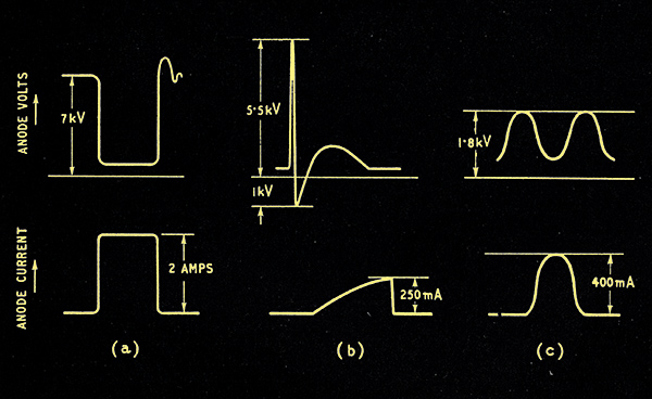
Fig. 1. Typical operating conditions of voltage (above) and current (below) for various types of power valves: (a) pulse modulator, (b) line output valve, and (c) class B amplifier. Volts and current are not to scale. .
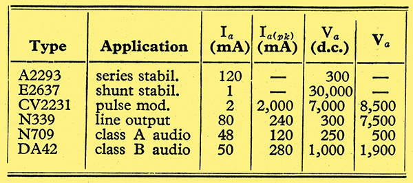
Although at first sight the desired characteristics for all types of power valves of comparable wattage rating are similar, they do in fact differ considerably, so that, apart from the control-grid characteristic mentioned above and the need for a high anode loading, they have little in common. Fig. 1 and Table 1 show typical operating conditions for various types of power valves using a similar cathode.
Stabilisers
There are two classes of valves here, one suitable for use as series stabilisers and the other for use as shunt stabilisers. The former are used in series with the load and must themselves absorb as little power as possible. They must be essentially low-impedance devices, and, for this reason, pentodes, either used as such or triode-connected, are frequently adopted. However, of recent years several low-impedance triodes specially designed for series stabiliser use have become available. The low-impedance requirement entails the use of close electrode spacing, and since a good grid control characteristic is of no great importance the grid wire spacing is made as wide as mechanical rigidity will allow, so that such valves have very low amplification factors, usually between 2 and 5. Working as it does under DC conditions the anode current of the series stabiliser is almost constant throughout operation. It is therefore unique among power valves in that its cathode need not supply a peak current greatly in excess of the mean current, and the cathode temperature of this class is often lower than that of other valves of a similar size and mean cathode current rating. In fact, the efficiency of the modern coated cathode is such that the ultimate loading of the series stabiliser is usually determined by the temperature of the anode or valve envelope rather than by the available emission.
Since ease of valve production is largely set by the mechanical strength of the electrode structure, there is a lower limit of anode impedance below which it is hardly economic to go, and the valve designer has to accept the limitations imposed by small-clearance electrodes. This has led to the efficient series stabiliser usually having a cathode current rating of about 150 mA, and although valves are made to handle much larger currents they usually consist of a multiplicity of these small units arranged in parallel within a common envelope. It is unlikely that a valve capable of handling high currents with a single electrode system will become available for some time to come, and it is probable that the most efficient and economic way of stabilising such currents will be by the use of a number of small mass-produced valves in parallel. A basic circuit of a typical series stabiliser unit is shown in Fig. 2.
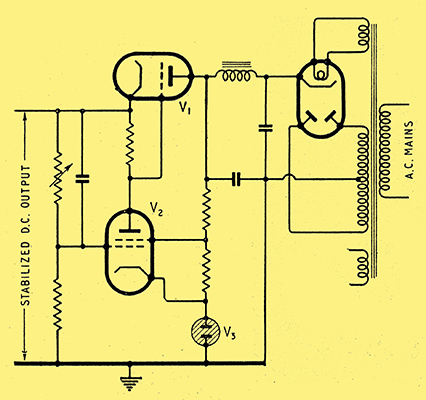
Fig. 2. Typical series stabiliser circuit. V1 is the series stabiliser valve, V2 the control amplifier valve and V3 the voltage reference tube.
Up to now shunt stabilisers have not been widely used in this country, but the increasingly high voltages needed for television and equipment such as radiation monitors will lead to their greater application in the future. The shunt stabiliser is essentially a high-impedance device, usually operating at a high anode voltage. Triodes are generally used and valves specially designed for this purpose often have cathode and grid structures similar to those in cathode-ray tubes. Single valves are invariably used.
Pulse Modulators
A pulse modulator is required to amplify voltage pulses from an earlier stage and to feed them into the drive circuit of a larger output valve. The load will be a coupling transformer and will be highly inductive. The operating voltage of the output valve may be quite high, often some thousands of volts, and this high DC voltage will have to be held off by the modulator during the quiescent part of the duty cycle. When the drive is applied the grid of the modulator is taken up to a high positive value and the peak anode current is very large. At the same time the voltage dropped across the load causes the anode voltage to fall to quite a low value. As soon as the drive is removed the anode current and voltage return to their original value, the inductive load often causing the voltage to 'overshoot' by a large amount unless an inverse diode is fitted. The electrical requirements of a pulse modulator are, then, that it shall operate at a high anode voltage, have a low impedance (otherwise the power loss when driven would be excessive), and be capable of a high cathode emission. Since the anode current must be zero during the quiescent period (when the anode voltage is very high), the valve must have a good grid control.
Obviously these conditions can only be met by the use of a tetrode or pentode. The cathode current density during operation is high, so that suppression of secondary electrons from the anode readily occurs and conventional forms of suppression by a third grid or beam plates are often unnecessary. The high cathode emission required is usually obtained by operating the cathode at an increased temperature. This, coupled with the fact that during the bulk of its duty cycle the pulse modulator is non-conducting, causes a fairly rapid increase in cathode interface resistance, so that the life of such valves is usually appreciably shorter than that of other valve types of a comparable mean power rating.
When the length of pulse handled is extremely short, less than a microsecond, the rate of rise and fall of anode current is so high that the valve is effectively handling a high frequency signal. Under these circumstances the valve inter-electrode capacitances must be kept low if distortions of pulse shape during amplification are to be avoided.
Line Output Valves
To a very limited extent the characteristic requirements of the line output valve are similar to those of the pulse modulator. Both valves require a low impedance while passing current and a very high impedance during the non-conducting portion of the duty cycle. Here the similarity ends. The line output valve works at a fairly high mean anode current with a peak/mean current ratio of about 3:1 only; the anode voltage rises to a high value for only an extremely short time during each cycle of operation and may then overshoot negative with respect to the cathode. The drive is such that the grid voltage does not reach a high positive value with respect to the cathode, so that the suppression of grid emission does not present too difficult a problem as the grid dissipation is small. On the other hand, the screen dissipation tends to be quite high, often approaching that of the anode itself, and careful attention has to be given to the prevention of screen emission. As in any output valve, currents to the anode which are not modulated by the control grid will cause loss of output. In the case of the line output valve, emission from either control or screen grid, being thermal in character, will cause a gradual loss of scanning width as the valve warms up.
The fact that variations in output are being constantly monitored visually by the user make it advisable for line output valves to be rated far more conservatively than, say, audio output valves, where output is usually readily adjusted by means of a volume control and has the added grace that the ear is far more tolerant of distortion than is the eye.
Low Frequency Amplifier Valves
These form the largest class of small power valves. They are used for the output stages of domestic receivers, public-address and high-quality sound reproduction equipment, speech reinforcement systems, servo motor control systems and countless other applications. Valves used in domestic radio sets invariably follow the fashionable design pattern of the day so as to suit mass-production requirements in both the valve and the receiver factories. For example, if a new base or bulb shape is introduced, within a very short time a complete new range of valves, often having a similar performance to previous ranges, will become available in the 'new look'. This means that many valves are used in equipment before they have had time to establish themselves as sound commercial products and before their users have had time to understand their particular peculiarities. The resulting unreliability, which is by no means peculiar to radio valves, is all too familiar to both radio dealers and the general public alike.
When the equipment has to give a public service, as with public-address or radio relay systems, reliability of operation is of extreme importance. The service must not have repeated breakdowns or its popularity will suffer. A valve type which has a consistently good life will give a service in which replacements can be made on a routine basis and not as a result of failure during operation. Economy is of importance, but more in consideration of replacement and servicing costs than in initial outlay. Consequently makers of such equipment have used known and trusted valve types of proved reliability for years on end and have been understandingly reluctant to risk their reputations by introducing valves of a more modern design. The designs of many of the valves used in public-address equipment to-day are approaching twenty years old: a long time indeed in the electronics industry!
Recent Trends
During the post-war years valve manufacturers have been cautiously trying to improve established types and incorporating improvements only after very extensive life testing covering many thousands of hours under operating conditions. These improvements have taken two main forms.
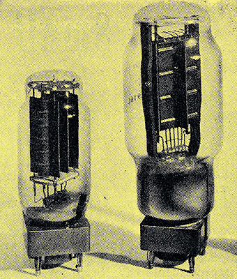
Fig. 3. Illustrating the redesign of a 100-watt anode dissipation audio output triode. The modern version is on the left.
In the first case valves have been wholly or partially redesigned to make them easier to produce or to avoid the continued use of obsolete components which may, during the course of several years, have become peculiar to one particular valve type. An example of such redesigning is shown in Fig. 3. In this case a well-known valve, first made some twenty years ago, has been completely redesigned. A more robust filament system, having fewer loops of heavier material, is used. New grid-treatment processes allow the grid to operate safely at a higher temperature than hitherto so. that its size can be decreased and the anode loading, which greatly influences grid temperature, can be increased. The consequent use of a lighter anode structure has allowed the designer to dispense with the rather clumsy system of anode supports previously used, and the whole valve is more suitable for modern manufacturing technique with its emphasis on economy in the use of materials and man power. A slight reduction in overall size has followed, but this was not a prime intention in the redesign.
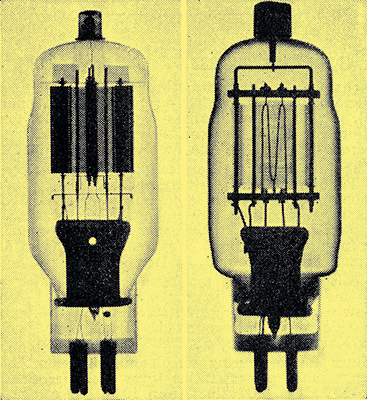
Fig. 4. Radiograph of two triodes having anode dissipations of 2-40 Watts. The valve on the right (DA41) is the older filament type, while the one on the left (DA42) has an oxide-coated cathode and is suitable for mass production.
In this case the new valve is a direct replacement for the old and retains the same type number. In the second case an entirely new valve may be introduced which is not essentially a plug-in replacement for the original type but which will, it is hoped, be used when new equipment is designed; or with minor circuit modifications will replace it in existing equipment. This has been done when the existing valve has features which make it unsuitable for modern usage. For example, a certain small class-B output triode has a thoriated tungsten filament. The inherent fragility of this type of filament and its extreme sensitivity to operating voltage make it unsuitable for use in mobile equipments or industrial applications where there may be some vibration present or where the mains voltage may fluctuate wildly. Consequently, a new valve has been developed which, while having the same operating characteristics as the original, is more suitable for modern requirements. The thoriated tungsten filament system has been replaced by an indirectly heated oxide-coated cathode, with consequent saving in cathode heating power. Since the grid of a valve having such a cathode has to work at a lower temperature than that of one having a thoriated tungsten filament, the grid of the new valve has larger diameter support wires, welded-on radiators, and is specially processed to avoid grid emission. The original anode, which was machined out of solid carbon, has been replaced by a fabricated metal structure and mica insulators are used instead of the ceramic ones. The temperature of the glass foot tube has been reduced by fitting a polished metal reflector between it and the electrode system. Fig. 4 is a radiograph showing the essential constructional differences of the two valves, while Table 2 gives a list of the materials used for their electrodes.
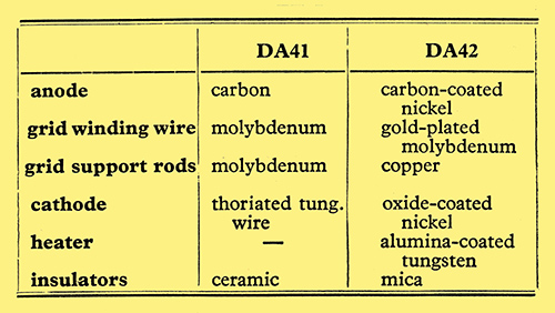
Table 2.
Economy in operation is influencing valve design to an increasing degree. The use of high-impedance valves in push-pull class-B operation is becoming more popular when power outputs of 30 Watts or over are required. Such valves operate when quiescent at zero grid voltage and require no bias supplies, although, of course, a low-impedance driving stage is needed. High peak anode currents are obtained by driving the grid well positive with respect to the cathode so that a high power output can be achieved without the use of excessively high anode voltage. The efficiency of circuit arrangements of this type can be as high as 66% and a pair of valves of the type shown in Fig. 4 can give an output of 175 Watts at about 5% distortion for a total input of 275 Watts. Since this type of circuit calls essentially for high-impedance valves, triodes are usually used and their relatively large electrode spacing and close pitched grids ensure very little characteristic variation from valve to valve.
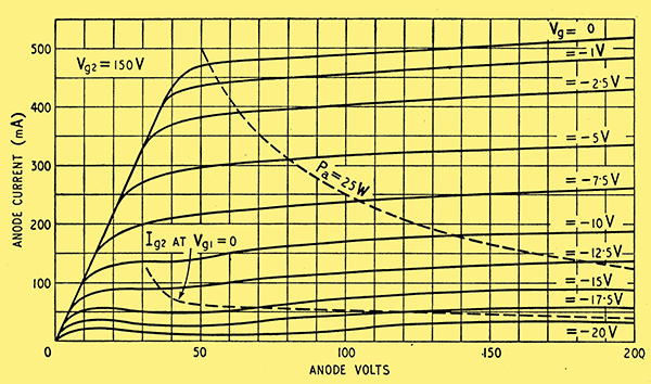
Fig. 5. Characteristics of a typical low-impedance output tetrode (KT55) suitable for use in high-quality amplifiers.
For low power needs - high-quality audio amplifiers for example - a reduction in equipment costs may be realized by the use of the specially low impedance pentodes and beam tetrodes which are now available. The characteristics of a typical valve of this type are shown in Fig. 5. It will operate directly from the mains via a metal or valve rectifier to give an output of 25 Watts from a pair of valves operating in push-pull, with a line voltage of 220 Volts. The heaters are connected for series operation. It can also be used as an inverter to provide a source of AC to operate, for example, gramophone motors from DC mains, and is quite a useful series stabiliser. Constructionally it consists of two separate cathode, control-grid and screen-grid systems mounted inside a common suppressor and anode system. Separate electrode systems are used to avoid the loss in mechanical strength and lack of characteristic uniformity which usually occurs with close electrode spacings in a large valve.
Trends of this sort must continue, and there will undoubtedly be a more extensive use of the pressed-glass base, which, since it is farther away from the electrode system, runs cooler and is less liable to failure than is the older glass-pinch type of foot tube.
|