|
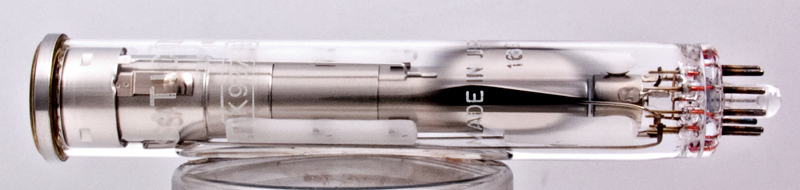
The K9373B Vidicon tube.
Ten years ago the task of generating a television signal was a job attempted only by the expert. Although the simple vidicon was on the market the majority of television pick-up tubes in use then were photo-emissive types which were more difficult to set up for good signal quality. In addition, the most important application of television was for broadcasting entertainment programmes where picture generation was largely confined to the big studios. Today the position is changing rapidly, because the comparative stability and ease of setting up of the modern vidicon (or one of its derivatives) has made it a camera tube that is suitable for a large number of applications. Among these are black-and-white and colour television broadcasting, aerospace telemetry, industrial and scientific CCTV, and amateur television. Further applications from a very wide variety are discussed below. The greatly enlarged range of tubes based on the vidicon has made it much easier to choose the best tube for the job, and many new applications have now been brought within the scope of the vidicon or its derivatives.
Now that a good CCTV system can be purchased for less than an audio hi-fi set-up[1] television signal generation, whether for a picture or not, is becoming increasingly within the grasp of the low-budget user in the industrial, educational, scientific and medical spheres as well as of the amateur and home user.
A review of the basic principles involved in generating a television signal is to be found here and in Ref. 7[7]. The present comments and tables are intended to help make the vidicon a much more familiar device to those people whose primary task is not the generation of pictures for television broadcasting. To do this well still needs the co-operative skills of equipment manufacturers, lighting experts, cameramen and technicians in a studio. This article should be helpful to the ever-increasing number of users who now use a vidicon with much the same confidence as they select and use a photographic camera or a transistor.
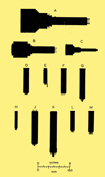
Fig. 1 Silhouettes to scale of modern vidicons and tubes based on the vidicon. A, intensifier vidicon; B, Esicon or SEC tube ( TH-CSF and Westinghouse); C, Ebitron (EMI); D, F, G, H, K, L, M, various vidicons; E, integral-coil vidicon (GE); J, Printicon (EMI).
The vidicon has lent itself to modifications more than any other pick-up tube. Fig. 1 gives some idea of the present-day range of tubes the selection shown here is by no means complete.
Most modifications to the basic studio broadcasting versions have been in the directions of matching the spectral response to regions of the electromagnetic spectrum outside the visible and increasing the sensitivity in weakly illuminated conditions. Other special versions, however, are made for extra-high resolution pictures, for severe environmental conditions such as vibration or nuclear radiation, for applications where size is a constraint, for portable light-weight transistorized cameras, for slow-scan TV, and for colour broadcasting cameras.
Roughly speaking diameters of basic vidicons (excluding coils) range from 13 to 43 mm and lengths from 86 to 265mm. Almost the entire electromagnetic spectrum can be covered, from 200 keV X-rays (8 pm) through the UV and visible to 2.4 microns in the IR. Sensitivities range from minimum target white light illumination levels of 1.0 - 10.0 lux for a simple broadcast quality or visible-light industrial quality vidicon to 10-2 lux for an intensifier vidicon or SEC tube. Light levels producing a total incident light flux on the target of less than about 10-6 lm (0.01 lux on the faceplate of a 26.7 mm diameter vidicon) give rise usually to a more or less 'laggy' picture, that is, one in which the signal generated by fast moving objects becomes smeared because a small amount of image retention occurs, fading in the tens of milliseconds range.
Vidicons vary over wide limits in this respect, but the lead oxide types in particular have very low lag. Other types are manufactured to provide an extended lag response for special applications (see Table 5). General broadcast and industrial quality vidicons are increasingly used to generate particularly high quality and stable television signals whenever the scene illumination is capable of being maintained at a reasonably high level. Examples are TV film scanning or remote studio application, as well as many industrial scientific, educational, and CCTV uses where lighting can be readily controlled, or where broadcast-quality short lag is not demanded with very fast moving scenes.
Leaving aside for the moment the question of lag, target illumination levels, lower than 10-2 lux cannot be used at standard picture repetition rates because the video output signal from the vidicon becomes very noisy due to the particulate nature of the light. However, target illumination levels below 10-3 lux can be used by integrating the signal for several tens of seconds on a special slow-scan vidicon (see Table 1).
If a lens optics system is used and the various tubes are put in order of white-light sensitivity (defined as video signal output for a given scene brightness), the list is as follows: Ebitron secondary electron conduction (SEC), intensifier vidicons, silicon and lead oxide vidicons, 22 mm vidicons, 13 mm vidicons. For a given depth of focus, the sensitivity of a camera using a lens system and a vidicon with a linear light transfer characteristic depends only on the f-number of the optical system and the vidicon signal output for a given number of lumens incident on the faceplate. Thus the camera sensitivity does not depend on tube diameter unless fibre-optics is used exclusively, in which case the sensitivity is greater for large diameter fibre-optics faceplate vidicons.
Manufacturers tend to specify in different terms the sensitivity of tubes in which the light transfer characteristic is not linear, since questions of light and signal level, dark current and emergence of background blemishes all need to be specified unless purely subjective criteria are used.[9]
This is a long table - click image for full version.
Key to applications recommended by manufacturers.
A dagger beside a dimension means inclusive of integral coils; * see figure 2 a, amateur and home use; b, black-and-white live-scene studio broadcasting; c, colour live-scene broadcasting; c, CCTV and industrial live-scene colour; d, data transmission; e, educational black-and-white; E electrostatic; f, may be used without face-plate discolouration in areas of high radiation; g, general purpose; G, US government end-use only; h, high resolution; i, industrial; i' extra high quality industrial; I, integral: j, internal reticule; k, caption scanning; L, low light level; m, military; M, magnetic; n. aerospace; o, obsolescent replacement type; p, low priced economy tube; q, extra high picture quality; r, relaxed blemish specification; R, ruggedised; s, scientific; S, development tube available on sampling basis; t, telecine (TV film scanning); t, colour telecine; u, integral coils, U, underwater television; v, very high pressures; w, lightweight cameras; x, experimental use; Y, slow-speed scan; z, suitable for viewing X-ray fluoroscope screens; S, separate mesh.
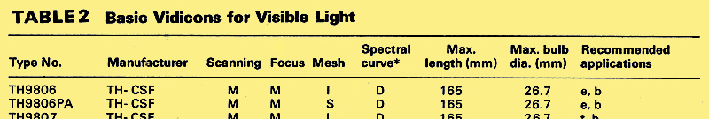
It is thus a simple matter accurately to compare the sensitivities of the silicon, lead oxide and ultra-violet types of vidicon, the SEC tube and the Ebitron, but not those of intensifier vidicons, or standard types for visible light applications, as shown in Table 2. These tubes have a less-than-linear light transfer characteristic and thus have a higher sensitivity at low light levels. Uniformity of dark current is more important than its absolute value, since all that is needed in the video channel to compensate for a constant dark current is admixture of a DC potential, although manufacturers of broadcast-quality colour cameras prefer negligible dark current. The foregoing list can therefore only be used as a guide.
The usual video bandwidth for a high-resolution flicker free television picture is between 3 and 10 MHz at which all public entertainment broadcasting is undertaken. However, this is not the optimum for a high signal/noise ratio at low light levels in those applications where picture flickering is not troublesome, but is obviously linked to the picture repetition rate and the resolution required. Provided that the bandwidth is no higher than that needed for the resolution, the highest signal/noise ratio obtains at about 300 kHz for a 405-line picture. The exact scanning conditions may be readily calculated from the analysis given in Ref. 1[1]. The enhanced signal/noise ratio results from employing the same number of scanning lines in the picture and the same horizontal resolution, but a lower video bandwidth and a slower frame rate.
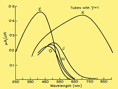
Fig. 3 Spectral sensitivity curves for various types of vidicon target in which the light transfer characteristic is linear.
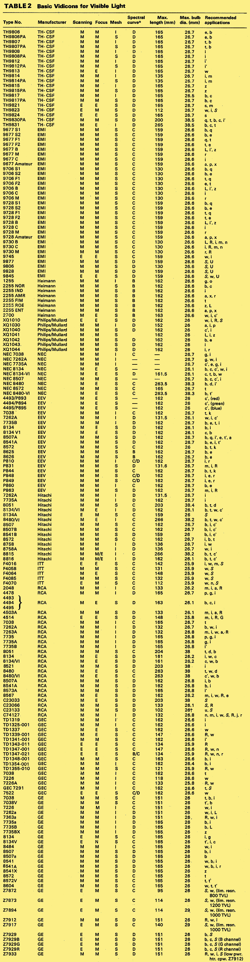
Basic vidicons for visible light applications
This is by far the largest category, because tubes of this kind are widely used for applications which include broadcasting, CCTV, industrial, educational and medical purposes, missile telemetry, space TV and telecine (film scanning). Earlier tubes were specified to a larger extent than now by subjective criteria, such as whether a television picture looked good or whether there were many background blemishes visible. Such valuable tests are always made, together with others, on all tubes, especially those employed in entertainment television. However, particularly since the introduction of multi-tube colour cameras, a much greater emphasis is placed on specifying more objective measurements such as light transfer characteristic, spurious signals, stability against light overload, and picture lag[10]. Therefore it is now possible to select a tube with much greater precision than formerly, provided that it is possible clearly to define tube requirements; this tends to be easier to do in scientific and industrial applications, and is more important in the design of colour cameras for broadcasting.[10]
The electron beam can be scanned and focused either magnetically or electro-statically; this gives rise to four possible varieties of vidicon. Highest resolution tubes employ magnetic deflection and focus, next in resolution capability come those with magnetic focusing or deflection and electrostatic deflection or focusing, and then come the all-electrostatic tubes. The latter are capable of yielding the smallest cameras for a given target size, and are particularly well suited for small light-weight transistorised cameras of low power consumption, or for industrial uses where space is at a premium.
The most common and significant variation in electrode structure of all-magnetic tubes is the connection to the mesh electrode. (g4), which may be internally connected or brought out separately. Although separate mesh tubes require an extra voltage, a big gain in resolving power is attainable[8]. The optimum ratio of mesh to g3 voltage for best geometry or for best uniformity lies in the range 1.2/1 to 1.7/1 depending on the scanning and focus coils used. The mesh should always be operated at a higher potential than g3, otherwise most of its advantages are lost; in electrostatic tubes, g5 is the separate mesh and this must be operated at the manufacturers recommended voltage.
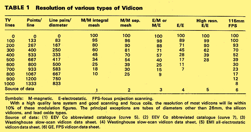
It is difficult to make a strict comparison between the resolving powers of tubes made by different manufacturers because different ways of specifying this are often used. Limiting resolution is a subjective estimate so it cannot be used with precision, especially when different people make the test; a rough quantitative figure would be 2-3% output signal compared with the very low frequency output at the same light level. This is modulation depth. Other ways of quoting resolution depend on specifying the modulation depth of a given number of spots per line or number of TV lines.
Table 1 summarizes the resolution figures for different types of vidicons, together with conversions from different ways of specifying this.
It must be emphasized that in magnetically scanned tubes, such factors as resolution, deflection defocusing and scanning orthogonality are very much a function of the scanning and focus coils used. The new printed-circuit scanning coils eliminate many of the disadvantages of the older kinds[3].
Obviously, the tables and comments can in no way replace the more detailed information to be found in the manufacturers data sheets. An exact price for any country in the world may be obtained from his agent or from one of the manufacturers listed in next months article. Prices range from about £10 for an economy or amateur-grade standard vidicon to £135 for a broadcast-quality tube; lead oxide types tend to be somewhat higher, and these range from about £500 to £6OO for broadcast quality tubes, with £300 or so for industrial tubes and £50 each for setting-up tubes.
High sensitivity tubes
Since a vidicon type tube generates no noise, the signal/noise ratio of the video output signal depends on the signal level and the design of the TV head amplifier[1]. All commercially available TV systems incorporate a head amplifier designed so that the noise is minimized. However, in a standard television system employing a modified vidicon with a pre-scanning gain of 15-40, the signal/noise ratio is determined less by the head amplifier than by the shot noise in the photo-current.
It is possible to achieve a system signal/noise ratio nearly equal to the primary photo-current noise, which itself is very close to the signal /shot-noise ratio in the light-hence the term ultimate sensitivity is often applied to these tubes. To attain this limit at very slow scanning speeds may require an even larger pre-scanning gain to give an output signal of about 150 nA; this extra gain might be obtained from, for example, a separate image intensifier. A further advantage of operating the vidicon scanning section at a signal output level of about 150 nA or more is that the lag is negligible with one of the photo-conductors shown in Fig. 2, B, C, D, or Fig. 3, G, H or J.
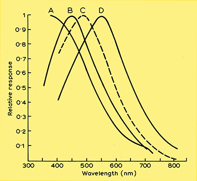
Fig. 2 Spectral response curves for various vidicon targets in which the light transfer characteristic is not linear. Similar response curves do not imply identical targets; in particular, factors such as dark-current uniformity and resistance to 'burn-in' may be different as well as other parameters.
Pre-scanning amplification may be achieved through incorporation of an image intensifier fibre-optic coupled to a fibre-optic vidicon (intensifier vidicon); through electron bombardment induced conductivity (Ebitron) or the phenomenon of secondary electron conduction, (SEC tube or Esicon). Profiles of these tubes to scale are shown in Fig. 1.Spectral characteristics of photo-emissive cathodes used in tubes of this type are shown in Fig. 4.

Fig. 4. Spectral response curves for photoemissive cathodes.
Vidicons with fibre-optic faceplates (which have an effective f/1.0 optical system) are shown in Table 3.
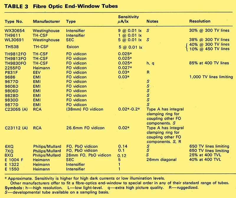
These vidicons may be compared directly with the intensifier vidicon and the SEC tube since these also employ fibre-optics input systems. The important sensitivity criterion here is μA/lux. specified with the faceplate area, and not μA/lumen alone, which is the sensitivity specified for any tube employing lens imaging. Such fibre-optic end-window tubes can be coupled directly to other fibre-optics devices such as a light-pipe or an image intensifier, or used for in-contact film scanning and applications such as image conversion by using a phosphor deposited directly on the fibre-optic window.
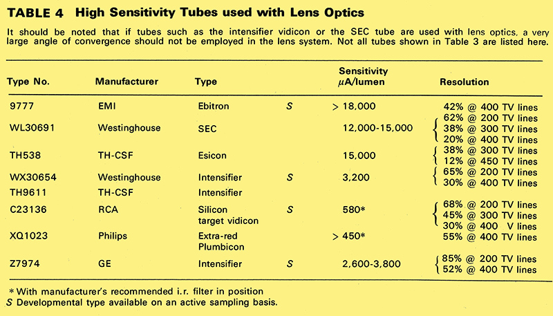
Since conventional lens optics maybe used with tubes employing fibre-optic faceplates provided that very high f-number lenses are not used, it is possible to compare all high-sensitivity tubes. Table 4 compares the sensitivity of these tubes when used with conventional lens optics of not too high light-convergence angle. Their use for satellite astronomy has been proposed.
Storage vidicons
It is often necessary to retrieve information from a television signal waveform as a repeated sequence of outputs. Two types of vidicon are made specially for this application.
In the first type, the target of the tube is so designed that the signal decays very slowly with successive scans; this is brought about partly by a slow decay of photo-conductivity, and partly through the electron beam scanning off only a small proportion of the available charge pattern in each sweep. Tubes of this kind are used in PPI to TV scan conversion for bright distributed radar displays, and in other applications where it is necessary to separate the functions of display and storage.
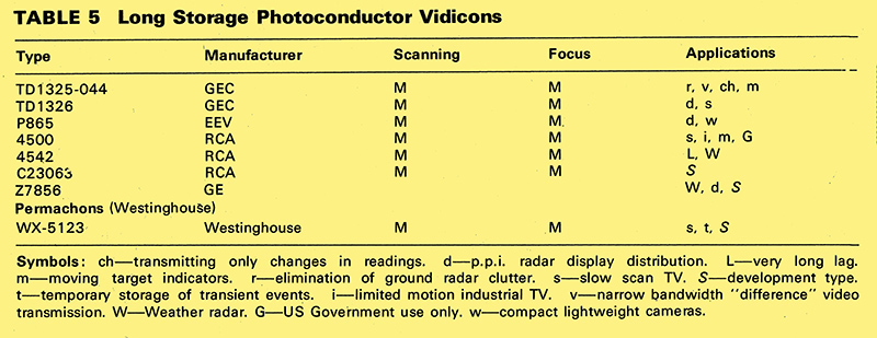
The target in the second type of tube, the Permachon, is capable of regenerating the scannedoff signal, to permit continuous reading for up to 30 minutes. If erasure of the stored information is required, this may be done quite simply in a single scanning period by interrupting the scanning beam. An alternative version uses a separate gun to write-in the information, but otherwise the storage properties of the target are the same. This scan-conversion Permachon can be use- fully employed in TV systems conversion as well as for other purposes where somewhat greater flexibility is required than is available with the first type (Table 5).
References
- P Rainger, A camera tube head-amplifier. Roy Tel Soc Journ. 11, 230, (1967).
- CCTVFrom Novelty to Necessity. Wireless World, Nov. 1968.
- E W Bull, Printed Scanning Coils. Wireless World, Aug. 1968, pp. 260-262.
- R Barer & J. Wardley, Ultra-violet television microscopy. Nature, Dec. 16th 1961.
- J Wardley & F W Jackson, Advances in Electronics and Electron Physics, 1969.
- H G Lubszynski, B J Mayo, J Wardley and N C Barford. 'New all-electrostatic vidicon. ProcIEE, March 1969, p. 339.
- R T Clayden, TV picture generating equipment in Video Techniques, Electronics Data Library, vol. 3, 1969.
- H G Lybszynski and J Wardley, Some problems of resolution in low-velocity camera tubes. ProcIEE, June 1963, p. 59.
- H G Lubszynski, S Taylor and J Wardley, Some Aspects of Vidicon Performance, J Brit IRe, May 1960, p. 325.
- I J P James, The EMI Four-tube Colour Television Camera. Part 1 The Design Philosophy. Radio and Electronic Engineer, 39, 249, May 1970.
|