|
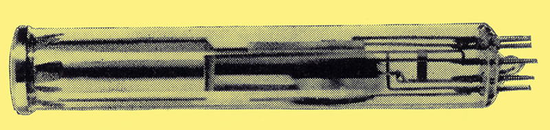
The Mullard vidicon television camera tube, type 55850, has been designed for industrial, medical and broadcast closed-circuit television systems. In this article, the principle of operation of this tube is briefly outlined.
Closed Circuit Television
How often, when touring an exhibition hall are we confronted by our own image appearing on a television screen on some stand or other? Or how often do we see clusters of people around a shop window attracted by a closed-circuit television display? CCTV possesses the appeal of novelty and as such can be a useful adjunct to sales promotion. But it also offers an advantage of a more serious nature in that it allows a larger audience to be reached than would otherwise be possible.
In other walks of life, too, the serious application of CCTV is increasing markedly. Its use in hospital operating theatres where it allows students to witness intricate surgery is widely appreciated. In fact, in this field, even colour television is quite commonplace.
The potential of closed-circuit television in the wider field of education is gradually being realised. A system has recently been installed in a Buckinghamshire Grammar School to offset the shortage of mathematics teachers. Its possible use to allow closer observation of 'live' practical demonstrations is an obvious extension of the medical application of closed-circuit television, and illustrates how such systems can be used to augment the traditional methods of teaching.
In the County Hall, London, the LCC has recently installed a closed-circuit system to televise the proceedings in the Council Chamber. Its purpose is to keep councillors who are working elsewhere in the building informed of progress, so that they may return to the Chamber when items of particular interest to them arise.
In the industrial sphere, closed-circuit television is widely accepted as an indispensable tool. Observation of inaccessible places such as the inside of a furnace or the bottom of a dam is now possible, and the monitoring of dangerous operations or radio-active regions can now be undertaken in safety. Widely dispersed activities in large factories or on a building site can be readily controlled from a centralised position.
On the railways, CCTV is helping in the effective control of passenger and traffic movement. At a London Transport underground station, for example, it is being used to relieve over-crowding on escalators and in passages during rush-hour periods, while in the Western Region of British Railways, it is serving to establish a better service to and from the London terminus.
These are but a few of the instances of the growing use of CCTV. Many other examples could be cited, and many more potential spheres of application could be given. In all of these, the camera pick-up tube is as essential to the system as is the display picture tube, but its function may not be as familiar to the dealer and service engineer. In this short article, therefore, we propose to give a brief description of the construction and operation of an important type of camera tube - the vidicon.
The Camera Tube
The purpose of the television camera tube is to convert an optical image of a scene into an electrical signal. This signal is then amplified and transferred to the display unit, where it is translated back into an image of the scene.
The complete optical image on the face of the camera tube cannot be converted instantaneously into the electrical signal. It has to be broken down into a large number of small picture elements, and this is effected by scanning the image with a narrow electron beam. If this scanning is performed rapidly, the differences in brightness of the different parts of the optical image can be converted into a suitable electrical signal.
The Vidicon Camera Tube
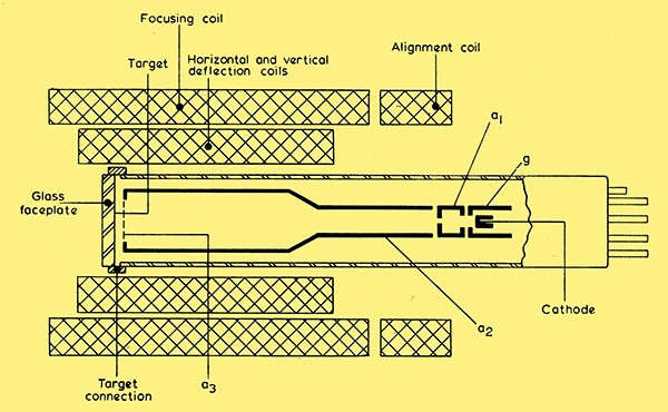
Fig. 1. Schematic diagram of vidicon and accessories.
A schematic diagram of a vidicon camera tube of the Mullard 55850 range and its accessories is given in Fig. 1. It is convenient to consider the vidicon in three sections: the electron gun, the scanning section and the target section.
The electron gun contains a thermionic cathode, the control grid g which controls the flow of electrons from the cathode, and the anode al which accelerates the electrons and confines them to a narrow beam by means of the small hole in its face.
The electron beam so formed enters the scanning section of the vidicon. This consists of a cylindrical focusing electrode a2 which terminates in a fine mesh electrode a3, the potential of which retards the electron beam. Surrounding the focusing electrode are the beam-centring, focusing and deflection coils. The focusing coil, together with the focusing electrodes, accurately focuses the beam on the target. The horizontal and vertical deflection coils cause the beam to scan the target. The beam-centring coil aligns the beam accurately along the axial magnetic field.
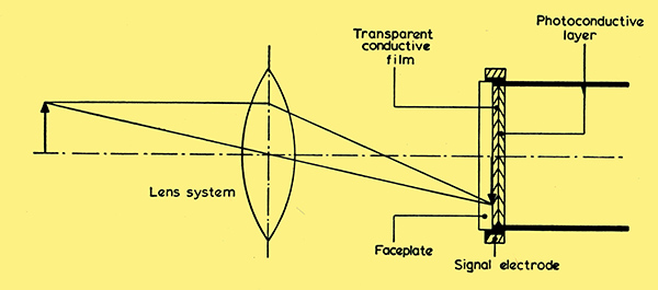
Fig. 2. Target section.
The target section of a vidicon is illustrated in Fig. 2. It consists of an optically flat glass faceplate, a transparent conductive film on the inner surface of the faceplate, and a thin layer of photo-conductive material deposited on the conductive film. The conductive layer is connected electrically to an external electrode, the signal electrode.
Principle of Operation
The resistance of the photo-conductive layer in the target depends on the amount of light that falls on the target. It is very high when the illumination is low, and vice versa. The optical image to be televised is focused by means of an external lens system through the faceplate and transparent conductive layer onto the photo-conductive film. The resistance of this film varies over the target area in a manner that depends on the light distribution over the surface, thus forming a 'resistive' image of the optical image to be televised.
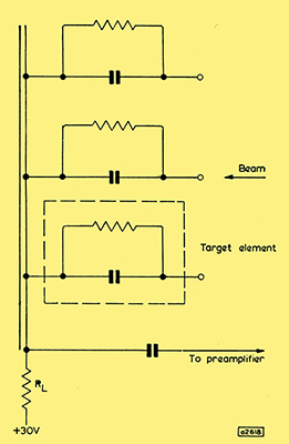
Fig. 3. Equivalent circuit of target elements.
As the electron beam scans the target, it effectively breaks the target up into a large number of elements. Each of these elements is electrically equivalent (Fig. 3) to a parallel combination of a resistance contributed by the photo-conductive layer and a capacitance formed between the photo- conductive and conductive layers.
During operation, the elementary targets are all connected by ways of the signal electrode to a load resistor RL and a positive potential of some 30 V. Initially, in the absence of the cathode beam, the potential of all the target elements assumes this positive potential. As the electron beam scans the photo-conductive surface of each target element, this surface will acquire approximately the potential of the cathode. A potential difference will thus be created across each elementary capacitor equal to the potential difference between the positive potential applied to the signal electrode and the potential at the cathode.
Dark Current
When there is no optical image on the target, the value of each elementary resistance will be high but finite (equal to the 'dark' resistance of the photo-conductive material). Consequently, the potential difference across the capacitor will slowly decay once the beam has scanned the element, and this leakage of charge will continue until the electron beam repeats its scan. When this occurs, the potential of the negative electrode of the elementary capacitor will again be reduced to that of the cathode, and positive charge will be attracted from the positive supply to the positive electrode of the capacitor. A momentary current will thus flow in the load.
This process is repeated for each elementary target once during every scanning period. There will thus be a series of momentary currents flowing in the load, and the composite current will be an electrical representation of the optical condition - in this instance, darkness - of the target. The current that flows in the absence of illumination is termed the 'dark' current.
Illuminated Target
If an optical image is focused onto the target, a corresponding pattern of electrical resistances is built up in the target elements. The leakage of charge across the elementary capacitor will therefore be faster or slower according as the illumination of that element is greater or smaller. Thus during one scanning period, a 'charge' image is created on the elementary capacitors corresponding to the optical image, and this charge image governs the extent to which the charge on the capacitor has to be replenished when the scan is repeated. In other words, it governs the values of the momentary currents flowing in the load, the currents being larger for greater illuminations of the target elements. During continuous scanning, the composite current flowing in the load will be a continuous representation of the optical image on the target, and as the image changes, the changing scene will be translated into the modulations of an electrical signal.
Mullard Vidicon Type 55850
The Mullard one-inch vidicon camera tube is intended for use in industrial, medical and broadcast systems and is suitable for mono-chrome or colour. It has been developed primarily for fully transistorised television cameras, but is also a notable addition to the range of pick-up tubes for cameras that use valves.
An indirectly-heated cathode is used in the 55850, and the heater consumption is only 0.6 W. The high sensitivity of the photo-conductive layer of the target ensures high-quality pictures in the normal lighting conditions of industrial applications. The tube will resolve up to 900 lines.
Three grades of tube are offered in the 55850 series. These are:
- 55850N, which is intended for normal industrial application;
- 55850S, which is suitable for medical, broadcast and industrial applications that require a higher quality picture;
- 55850F, which is designed for use in film scanners.
The electrical and mechanical properties of the three grades are identical. The only differences lie in the degree of uniformity and freedom from blemishes of the photo-conductive layer.
Data for the 55850 and information on operating conditions and equipment design are available on request to TID at Mullard House.
|