|
Patrick Mitchell looks at how the means of controlling a thermionic valve's emission have evolved and explains what the pros and cons of having multiple grids are.
While the power efficiency of valves is largely determined by the performance of the cathode, other important properties depend on the nature and geometry of the valve's grid, or grids. These properties are gain, linearity, distortion, band width, and to some extent noise.
The origin of thermionic valves is usually traced to Edison's 1883 patent for what he called an 'electrical indicator'. This was the first device to use current flowing through the space between a filament and another electrode. Edison recognised that this current would flow in one direction only, but he put this rectifying effect to no use.
J A Fleming had been appointed as scientific advisor to the Edison Electric Light Company of London in 1882. He became involved in research into the blackening of light bulbs with vaporised filament carbon - the same area that had led Edison to his 1883 patent.
Some examples of Edisons 'indicator' bulbs were brought to Fleming in the course of this work. He noted their rectifying property, but had no immediate application for it. The bulbs were to remain forgotten for several years. In 1899 Fleming was appointed technical advisor to Marconi's wireless company and began work on radio transmission and detection. At the time the weakest link in radio communication was the detector. The devices in use were the rather unsatisfactory coherers, as described in a separate section entitled Coherers.
Fleming realised that considerable improvements in detector performance could be achieved if a high-frequency rectifier could be devised. Edison's indicator bulbs were taken out of storage and tried as RF detectors. The experiments were successful. After making various changes to optimise RF rectification Fleming filed for patents in 1904 for his 'oscillation valve'.
Although in time thermionic devices would be used universally as detectors, they were not an immediate success. Other types of detector such as Marconi's magnetic detector patented in 1902 remained in use alongside the diode valve until the end of World War I. Rectifying RF signals was one part of the problem of detection. The very low signal power available from an antenna was the another. Truly satisfactory radio detection had to await the development of electronic amplification.
It was the development of a means of controlling the magnitude of the 'space current' that enabled valves to amplify.
This control mechanism was responsible for their transition from esoteric scientific instruments to valuable engineering components.
The well known grid was one of several means of achieving control that were experimented with. All methods shared the same principle: to control the field strength in the immediate vicinity of the valve cathode. If this could be achieved without introducing any additional currents then so much the better, but in reality it never was and never has been.
Lee de Forest is remembered as the man who put the grid into the diode valve. After receiving a PhD from Yale in 1899 on the reflection of electro-magnetic waves, de Forest - like Fleming on the other side of the Atlantic - began work on radio. He had noticed that gas lights in his laboratory flickered in response to electro-magnetic waves generated by sparks.
Having observed the flickering gas lights, de Forest spent several years experimenting with hybrid devices involving Bunsen burner flames and thermionic tubes in an attempt to find a better radio detector. This was to be a blind alley, but his involvement with research into detectors led him to acquire, and experiment with, several Fleming valves.
Early Grids
In connection with this work de Forest had a New York lamp manufacturer called McCandless make copies of Fleming valves. Some had extra electrodes of various configurations. Several US patents followed from this work, one of which, in October 1906, was for his first three electrode 'Audion'. This involved a type of Fleming diode with parallel plates on either side of the filament, connected together as the anode to maximise 'space-current capture'.
Wires to these two plates were brought out separately. One was connected to an antenna and the other to a detector. De Forest claimed that this arrangement was capable of amplification, which is doubtful, but he recognised that the current to one plate could be controlled by the voltage on the other.
De Forest reasoned that the performance of the device might be improved if the third electrode was placed between the filament and the anode. He realised that if a solid sheet were used it would largely block the current flow to the anode, so instead he specified a piece of wire bent in the shape of a grid iron.
The name grid stuck. He ordered some bulbs to this specification from McCandless which were delivered on 25 November 1906. At the time, de Forest was beset with legal and financial troubles stemming from patent law. Because of this, he did not test the new bulbs until 31 December. The tests showed that definite amplification was possible.
A patent followed on 29 January, 1907. De Forests 'Audion' was not, however, the first amplifying valve. European workers had been experimenting with the cathode-ray tube, described in a separate section entitled 'Cathode-ray amplifiers'.
Temperamental triodes
Early triodes were temperamental, varied widely in characteristics from one example to another and had limited life. These problems were investigated and gradually solved by engineers and manufacturers.
The main difficulties were the generation and maintenance of a high vacuum, and the production of durable filament cathodes. Being a fairly simple structure operating at lower temperatures than the cathode, the grid posed fewer problems and so changed little in the early years.
Mechanical strength, ease of manufacture and reproducibility led to the abandonment of the unsupported bent wire arrangement and the adoption of ladder type grids, but it was not until other problems had been ameliorated - if not solved - that the electrical properties of the grid began to limit valve performance.
In the years leading up to World War I, the development of the valve became mired in patent law. This was responsible for stagnation of the technology and financial troubles for the innovators and producers. As usual, the only winners were the lawyers.
Patents were suspended to allow development of military communications equipment to go ahead unhindered during the war. But the problem recurred thereafter and the need to avoid patent infringement prompted many novel arrangements - though few technical improvements.
The development of the grid and its geometry was dictated by three principle technical limitations: secondary emissions, microphony, and capacitive feedback - the Miller effect. Once the problems of consistency, reliability and life span had been addressed, the impetus was to increase the gain and raise the maximum operating frequency of valves.
General Electric appointed Dr Irving Langmuir as an engineer in 1909. He was to prove a valuable asset. GE had developed a high power 200kHz alternator for radio transmission but had no means of modulating its output. Langmuir thought that the triode might be adapted to make such a modulator and began a painstaking study of its electrical characteristics.
Several key improvements were to emerge from his work. An increase in gain by moving the grid closer to the cathode was the first improvement. Cathode current depends on the field strength immediately adjacent to the cathode. The closer the grid is to the cathode the lower the grid voltages needed to produce the necessary fields.
This modification had the happy side effect of increasing the distance between the anode and grid and hence reducing the anode-to-grid capacitance, which when amplified by the stage gain appears as Miller capacitance. The down side was increased grid heating and contamination with cathode atoms, leading to thermionic emission.
Suppressing emission current was to be a central theme in grid development. This is the exact opposite of what is required for cathodes. Incidentally, Langmuir was also responsible for noticing the potential of, and perfecting, the thoriated tungsten cathode.
Several factors conspire to cause grid emissions. The control grid is located near to the hot cathode to improve gain. This means that it is inclined to absorb vaporised constituents of the cathode - particularly as they are liable to be positively charged heavy ions and the grid is usually more negative than the cathode. Deposits of Ba, BaO2, and Th on grids caused by cathode evaporation increase their thermionic emissions.
Another effect of the close proximity to the cathode is that the grid gets hot.
Unwanted emissions
Secondary emission is the emission of electrons from a surface induced by high energy electrons striking it. The secondarily emitted current may exceed the incident current - an effect that is exploited in photomultipliers.
Electrons emitted from the cathode have a range of energies, a few of them having enough to cause secondary emission when they strike the grid. The bombardment of the grid by high energy electrons also heats it, exacerbating thermionic emission.
As the grid is usually connected in a high impedance circuit, a small current of electrons away from it can cause a significant potential rise, attracting more electron bombardment and further heating and thermionic emission leading to thermal runaway.
Suppression of grid emissions depends on choice of surface coating, geometry and voltage. It is eased by increasing the grid-to-cathode spacing and by using finer grid wires. Holding the grid at a negative potential relative to the cathode also helps. In most valves, grid current approximates to zero when the grid voltage is more than 1V below cathode voltage.
Grid coatings
Numerous coatings were tried to increase the grid's effectiveness and defeat the thermionic effect of condensed cathode atoms. Graphite was one of the first coatings to be used. Although effective, it is fragile and deteriorates with time.
In 1930, it was discovered that gold plating was particularly effective at suppressing grid emission in valves using an oxide coated cathode. This came to be the commonest method used. A layer 1μm thick is needed for effective suppression.
Gold coating is very effective at stopping thermionic emission but places a considerable constraint on grid temperature as gold evaporation from the grid will poison the cathode. Thoriated tungsten cathodes operate and higher temperatures than oxide coated so platinum - also an effective emission suppressor but without the tendency to evaporate and poison the cathode - is used.
Grid geometry
For the grids field to be fairly uniform at the cathode surface, the grid wires should be numerous and fairly distant from the cathode. Considerations of gain and emissions dictate otherwise.
In the event, many small-signal valves, such as the triode Western Electric 417A in Fig. 1, use uneven grid fields at the cathode. In this case the wires of the grid are 7.4μm in diameter, pitched at 65μm and placed 45μm from the cathode.
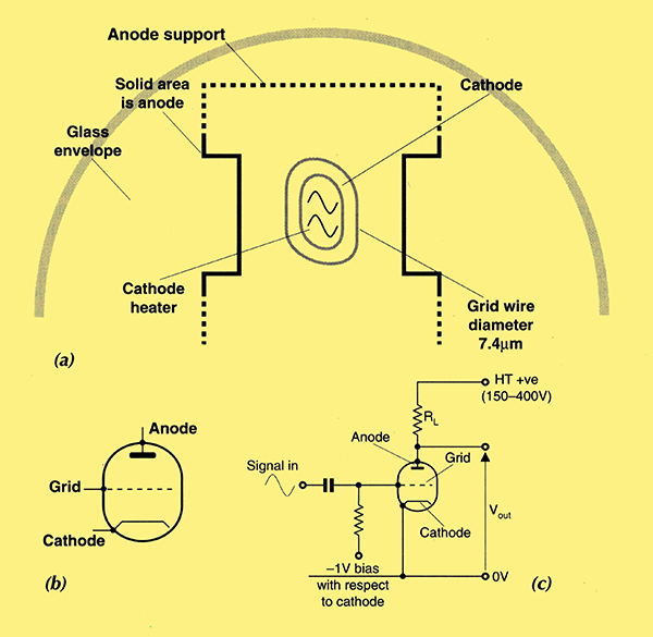
Fig. 1. The triode. Diagram a) is a cross section of the electrode assembly of a small-signal triode. Diagram b) is a circuit symbol commonly used for the triode and in c), a triode wired as a basic common cathode amplifier.
Valves of this type do not have a clean cut-off grid voltage as areas of the cathode close to a grid wire are cut off at smaller grid voltages than areas between wires. This led to a solution of the problem of automatic gain control. By altering the bias on the grid, a greater or lesser proportion of the cathode surface can be 'cut off' thus altering the gain. Beginning in the mid 1920s, this effect was augmented in some types intended for use as automatic gain-control components in radio receivers. They had grids with wires more widely spaced in the centre of the grid than at the ends and were known as 'vari-mu' valves.
Microphony in valve amplifiers is the appearance of a component of noise produced by mechanical vibration. The main cause for it is vibration of the grid wires. Microphony was of little relevance in the early days of valve production. As demand increased for radio equipment that would perform satisfactorily in aircraft in the late 1920s though, it became an important issue and research intensified.
The requirements of the grid structure preclude any effective damping scheme, but as most mechanical vibrations are low in frequency, the grid is constructed with a high resonant frequency. This is done by placing the grid wires under tension. They are generally made of tungsten, which has a high tensile strength. They are pulled to about half the breaking strain of tungsten and brazed with gold onto a molybdenum frame. The whole is then coated with gold.
The tetrode
Capacitance between the grid and the anode is the main factor limiting the operating frequency range of triode valves. Modifications to improve this were to increase the grid-to-anode spacing and to use fewer, narrower grid wires, but the effects of this strategy were limited.
In 1915 Langmuir at General Electric, and simultaneously Schottky at Siemens, addressed the problem by placing a 'screen grid' between the grid - now 'control grid' - and the anode, nearer to the control grid. The new valve was called a tetrode, Fig. 2.
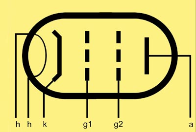
The circuit symbol for the tetrode.
A screen grid is connected to a low impedance circuit so its voltage varies little with variations in the anode voltage. The control grid is effectively screened from the anode. The screen grid's DC voltage must be higher than that of the control grid and cathode, or electrons will not pass it. In practice it is held at or near Vaa.
The frequency range of the tetrode was a substantial improvement over that of the triode but at a cost: distortion. Figure 3 shows a family of characteristic curves of a small signal tetrode.
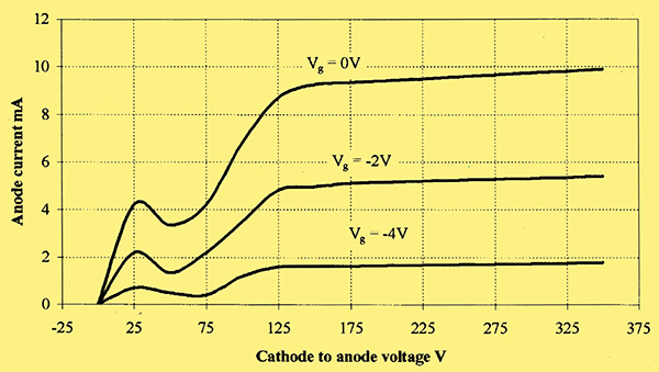
Fig. 3. V-I characteristic curves for a small-signal tetrode. The curves represent the relationship between anode current and anode voltage for various fixed control grid to cathode voltages (Vg). The kink between 25 and 75 V on the anode is due to the exchange of secondarily emitted electrons between the anode and screen. Notice the negative impedance between 25 and 50V.
Secondary emissions from both the anode and the screen are the problem. As a first approximation, the cathode current is shared between the screen grid and the anode in proportion to the relative areas they present to the oncoming space charge.
In practice, both the screen and the anode display a considerable degree of secondary emission due to high-energy electrons hitting them. Thus if the screen is more positive than the anode, current will flow from the anode to the screen and vice versa. This effect spoils the linearity of the relationship between anode current and control grid voltage by adding an undesirable dependence of anode current on anode voltage, seen as a kink in the I/V characteristic.
This nasty I/V characteristic was improved by increasing the grid-to-anode spacing and by coating the anode with an emission suppressing coating such as graphite. The basic problem remained however, and tetrodes - with the exception of beam power tetrodes - largely fell out of use as audio amplifier components by the 1940s.
Pentodes
Two Dutch engineers working for Philips, Gilles Holst and Bernard Tellegen, solved the problem of the tetrode by placing another grid between the screen grid and the anode. The result was the pentode and the new grid came to be called the suppressor grid, Fig. 4.
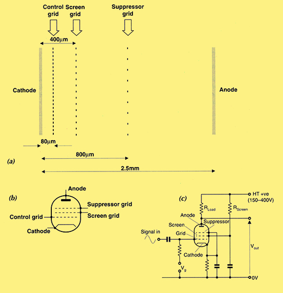
Fig. 4. The pentode - with a) showing an elevation view of the electrode assembly, b) the pentode circuit symbol and c) a pentode wired as a common-cathode amplifier illustrating typical biasing of the grids. Voltage Vg is around -1 V with respect to the cathode.
Philips was granted Dutch patents on the pentode in 1926 and patents around the world soon after that. This was one of the key developments that led to Philips establishing the dominant position it still enjoys today.
The suppressor grid is usually held at cathode potential. It thus repels electrons approaching it from either side and suppresses the exchange of secondarily emitted electrons between the anode and the screen grid. It does not intercept electrons passing from the cathode to the anode.
A suppressor grid has widely-spaced wires to minimise its influence on primary anode current, yet it still suppresses virtually all exchange of secondary electronic emission. The pentode offers several other advantages as well: effective control grid-anode screening, high anode dynamic impedance and high gain per stage.
The pentode became the most popular valve type by far.
Beam Tetrodes
The beam tetrode was developed after the pentode to avoid infringing the pentode patents. It overcomes the problem of secondary emission cur rents by exploiting 'space charge' geometry. The control and screen grids are aligned so that electrons not impacting on the control grid also bypass the screen wires.
Two beam-forming electrodes, as shown in Fig. 5, further control the space charge. These electrodes are connected together and form a fifth external electrode connection. This is why the valve is often called a beam power pentode.
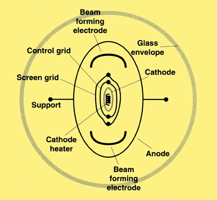
Fig. 5a. The beam power tetrode. Cross section of the electrode assembly.
The space charge is channelled between the grid wires and beam forming electrodes. In the area beyond the grids, the charge spreads out to reoccupy the gaps left by the grid wires.
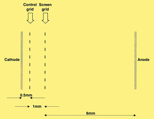
Fig. 5b. The beam power tetrode. An elevation view of the electrodes illustrating the alignment of the grid wires.
At any point in space within the valve, the potential depends on the voltages on the various electrodes and the space-charge distribution. The upshot is that the space-charge distribution is arranged to form a potential minimum down stream of the screen. This potential minimum acts as a virtual suppressor grid and repels electrons from both the screen and the anode.
The scheme works best when substantial space currents are present. This is why it is mainly used in high power valves - hence the term beam power valves. Beam power valves have very similar characteristics to pentodes, though their biasing is different so they cannot be used as plug-in replacements.
Semiconductors and the Return of the Triode
Triodes are less noisy than tetrodes or pentodes. Most of the noise in tetrodes and pentodes is partition noise.
To explain partition noise it is necessary first to digress to describe shot noise in valves. Electrons are emitted from the surface of a hot cathode according to a Poisson type process. The process may be regarded as purely random and thus has a noise component i2 = 2eΔf. This is a close approximation to the noise observed when the cathode current is saturated.
At currents below saturation, an effect called 'space-charge smoothing' markedly reduces this noise. In essence, what happens is that very close to the cathode there is a cloud of emitted electrons producing a potential minimum. Not all electrons will pass it.
If a large number of electrons are emitted locally then the depth of the minimum is increased and fewer electrons have the energy to pass it. This smoothes out the random fluctuations in cathode current and can reduce noise power by as much as fifty times. Space charge smoothing has little effect on the random distribution of electron velocity components parallel to the cathode. Because of the finite thickness of the screen and suppressor grid wires, the amount of current collected by them depends on the transverse velocity of passing electrons, so a random noise is re-introduced to the space charge smoothed current. This is known as partition noise.
Tetrodes and pentodes are affected by partition noise - but not triodes because they are usually operated with virtually zero grid current. Consequently, pentodes produce around ten times the noise power relative to triodes.
For audio applications, triodes also have better anode I/V characteristics than pentodes. There's more on this in a separate section entitled Characteristics and distortion.
Pentodes are stable, predictable, have a wide frequency range, and high output impedance. For these reasons they came to dominate the mass electronics market. Semiconductors though did these things better and have entirely replaced valves in that market, save for CRTs. But the particular properties of the triode have ensured it a niche in the growing high-quality audio sector.
Yet More Grids
Valves have been produced with four or more grids. The extra grids are usually extra control grids to allow mixing of several input signals.
Finally, I am indebted to Professor G M Sacchetti of Unison Research, Italy - makers of valve audio equipment - for his advice in the preparation of this article.
Further Reading
Saga of the vacuum tube, Gerald F J Tyne. ISBN 0-672-21470-9.1047
70 Years of Radio Tubes and Valves, John W. Stokes. ISBN 1-886606-11-0.
Principles of electron tubes, J W Gewartowski and H A Watson, 1965, Van Nostrand, Princeton, New Jersey.
|