|
Morgan Jones had 29 unused but old valves drawing on average just over a milliamp of grid current. Such a high current is unacceptable for small-signal valves, so he devised a method of bringing them back to life - and it works remarkably well.
Although the thermionic valve has now been obsolete for decades as a mainstream electronic device, there are still niche markets that use valves. As is well known, musicians use valve guitar amplifiers because of the distortion that can be produced under overload, whereas some hi-fi enthusiasts are willing to pay the high prices that valve equipment commands because of its legendary smoothness.
It is perhaps less well known that valves are extremely popular in recording studios, and that all the major microphone manufacturers feature at least one microphone with a valve head amplifier in their condenser microphone range.
Valve, or tube, microphones tend to be large capsule designs - around 18mm in diameter - and they are popular for vocals. Because a microphone level signal is, by definition, uncontrolled, it is not uncommon for recording engineers to want the entire vocal channel to have valve electronics until it reaches the channel fader. Consequently, other valve studio electronics includes outboard microphone channels, equalisers, and compressor/limiters.
Although the demand for audio valves has been demonstrated, in comparison with the electronics market as a whole, the audio valve market is minuscule. It is not worthy of significant investment.
Unfortunately, manufacturing valves is a high-technology enterprise, so production runs must be maximised, resulting in fewer than thirty different types currently being made. Worldwide, there is now only a handful of factories producing audio valves in significant quantities. Despite this, production runs are short, so quality control is difficult, and contemporary production engineers are having to rediscover the skills of their Cold War counterparts in the 1950s and 1960s.
The Cold War generated huge stockpiles of unused valves that are gradually released by governments. These valves are charmingly termed 'new old stock' - or NOS for short. There is a very great variety of NOS valves. Because these valves were made by manufacturers at the height of valve production, quality control is rarely an issue. As a result, many modern designers choose to specify NOS, rather than modern valves.
However, there can be problems with NOS valves. Scarcity can cause valves such as a NOS GEC KT66 to command a high price, so buyers will want to be sure that the product still meets its original specification - which is no mean feat after more than thirty years. To understand one of the most common problems of NOS valves, it is worthwhile to briefly review the physics of the thermionic valve...
Thermionic emission and diodes
All metals have free electrons within their crystal structure. Some of these electrons must be at the surface of the metal, but they are bound there by the nuclear forces between them and the adjacent atoms.
However, the atoms and electrons constantly vibrate due to thermal energy. If the metal is heated sufficiently, some free electrons may gain sufficient kinetic energy to overcome the attractive forces of the atoms and escape.
The heated metal in a valve is the cathode. When it is heated to a temperature determined by the work function of the metal, an electron cloud, or space charge, forms at its surface. Because electrons are negatively charged, and like charges repel, the cloud eventually attains a sufficient charge to prevent other electrons escaping from the surface, and an equilibrium is reached.
If a conductive plate, or anode, is placed some distance from the cathode, and charged to a positive voltage, electrons will be attracted from the cloud towards the anode. The electron cloud has now been depleted, and no longer repels electrons so strongly, so more electrons leave the surface of the cathode to replenish the electron cloud.
Current cannot flow in the opposite direction because only the cathode can emit electrons, and only the positive anode can attract electrons.
Electron Velocity
At the instant that an electron leaves the cloud, it has almost zero velocity, but it is constantly accelerated by the electric field between the cathode and anode, and acquires energy proportional to the accelerating voltage,
E = qeV = ½mev2
Rearranging, and solving for velocity,
velocity = √ 2V (qe/me)
The ratio qe/me is the electron charge/mass ratio. It has an approximate value of 1.76 × 10¹¹C/kg. If 100v is applied between the anode and cathode, the electrons will collide with the anode with a velocity of around 6×10⁶m/s, or 13 million miles per hour. Note that the cathode-to-anode distance is immaterial because an infinite distance would allow an infinite time for acceleration, so the collision velocity would still be reached even if the rate of acceleration was very low.
When the speeding electrons are abruptly halted by the anode, their kinetic energy is converted into thermal energy. It is this heat that is responsible for the anode dissipation rating.
Many effects within valves can be understood by having an appreciation of the collision velocity of the electrons as they hit the anode.
Ionization Current
The vacuum in a valve cannot be perfect, so there will always be stray gas molecules between the cathode and anode. As an electron nears the anode, it has considerable velocity. If it collides with a stray gas molecule, it may easily knock an electron from the molecule, which will promptly be captured by the anode.
Now, the gas molecule lacks an electron, so this positive ion is now accelerated towards the cathode in exactly the same way as the electrons were accelerated towards the anode.
Because a gas ion contains one, or more, neutrons, it is thousands of times heavier than an electron and does not attain the velocity of the electrons. However, if an ion manages to reach the cathode without being neutralised by a low-velocity electron, it collides with considerable momentum. It may be able to dislodge a molecule from the surface of the cathode. Unfortunately, the active surface of the oxide coated cathode in a small valve is only one molecule thick and therefore susceptible to damage by ion bombardment.
The Control Grid
In order to control the flow of electrons from cathode to anode, and produce amplification, a grid of fine wires is placed between the cathode and anode, Fig. 1.
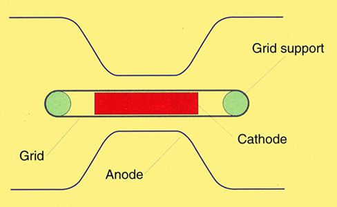
Fig. 1. Cross-sectional plan view of a 417A triode, drawn in proportion.
As you can see, to maximise its effect, the control grid is placed close to the cathode surface, where the velocity of the electrons is low, rather than near the anode, by which time the electrons have acquired considerable momentum, and are not easily repelled.
The Control Grid and Ionization Current
Valves are voltage-controlled devices and are operated in a similar manner to JFETs, in that the grid must be biased negatively with respect to the cathode in order to limit anode current [2] Valve Amplifiers, Morgan Jones, 2nd Ed. 0-7506-4425-7., Fig. 2.
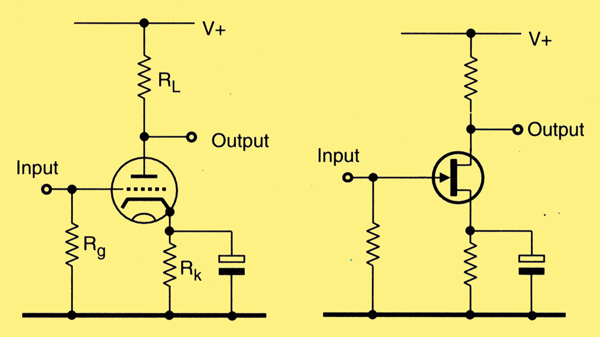
Fig. 2. Bias arrangements of thermionic triode, a), versus IFET, b). Both are voltage controlled and need a negative bias on their grid/gate to limit anode/drain current.
A grid-leak resistor, whose value is typically around 1MΩ, holds the the grid at 0V. The value of the cathode bias resistor in conjunction with individual valve characteristics determines the anode current because it sets the grid-to-cathode voltage, Vgk.
From the point of view of a gas ion, the grid and cathode are at very nearly the same potential, so they are equally attractive. As a result, the probability of a gas ion striking the grid is largely determined by the relative dimensions of the grid wire diameter and its pitch, Fig. 3.
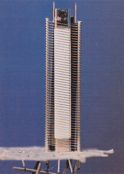
Fig. 3. 6080 power triode grid/cathode structure - note the gold plating on the grid to reduce grid emission.
As you can see, the grid wire diameter is quite fine compared to the gaps between the wires, so most of the gas ions strike the cathode. Whether the ions strike the grid or the cathode, they are immediately discharged by a balancing number of electrons flowing up through the external paths to ground.
Even though little of the ionization current flows into the grid circuit, it is usually the grid ionization current that is significant, not the cathode ionization current. This is because the external grid circuit typically has a much larger resistance to ground.
Bias Stability
If the ionization current is sufficiently large, it can develop a large enough voltage across the grid-leak resistor that Vgk is reduced, causing anode current to increase significantly.
Because power valves are usually operated at maximum anode dissipation, valve manufacturers specify a maximum value of grid-leak resistor to ensure that any change in Vgk due to grid ionization current is kept within safe limits.
Noise
Since the formation of ions and their subsequent discharge by the grid is random, the ionization current has a noise component. This current is converted by the grid-leak resistor into a noise voltage, and is amplified by the valve.
It is not unusual for high resistance circuits such as condenser microphone head amplifiers to use 500MΩ grid-leak resistors, so ionization current must be minimised to avoid degrading the signal-to-noise ratio.
Minimising ionization current
Clearly, the fewer gas molecules within the valve envelope, the lower the ionization current, so valve manufacturers strive to achieve as hard a vacuum as possible. During manufacture, the gas in the valve is pumped out, but some gas will remain that cannot be removed by pumps. This is removed by a structure called a getter.
The getter is a metal structure, often near the top of the valve, coated with a highly volatile powder - usually a barium compound similar to the cathode emissive surface. Once the valve has been pumped and sealed, the getter is exploded, consuming the remaining gas, and oxidising some of the getter material. The force of the explosion throws molten barium onto the inside of the envelope to give the familiar mirrored coating.
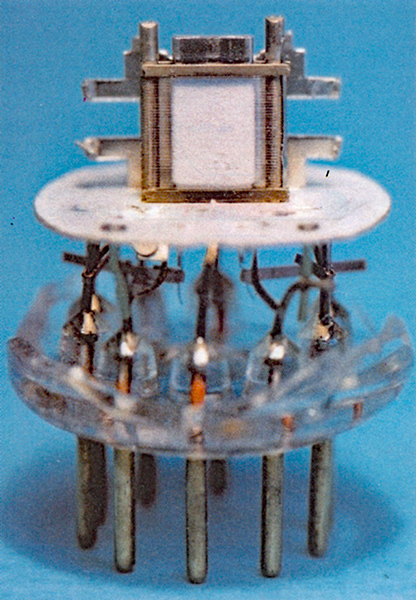
The explosion is initiated electrically. A heating current may be directly passed a through the getter's metallic supporting structure in the case of metal-envelope valves. For glass envelope valves, the getter may be shaped as a short-circuited loop aerial. In this case, the heating current is induced via an external RF field, Fig. 4.
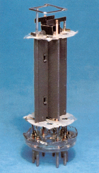
Fig. 4. A2293 power triode: the active getter material is in the trough completing the far side of the square loop aerial at the top of the structure.
Some of the getter material is inevitably de-activated by the explosion. The remainder continues to consume gas molecules throughout the life of the valve because gas inevitably seeps into the valve vacuum. It seeps in either via the seals, where the leads leave the envelope, or by out-gassing from a hot anode. Gas molecules must touch the getter to be consumed by it, and normal Brownian motion ensures this if the heater reaches operating temperature before HT is applied to the anode.
If the entire getter material is converted to oxide, perhaps because of a micro-fracture in the glass envelope, the mirrored coating turns white, so this is a clear evidence of catastrophic failure of the vacuum. Alternatively, very slightly gassy valves may still operate, but exhibit a gentle blue glow internally.
Softness
NOS valves are likely to have been sitting in a cold warehouse for at least twenty, and possibly fifty, years, so gas molecules will inevitably have permeated the envelope. In theory, the getter should consume the molecules to maintain the vacuum, but the most common cause of failure in unused valves is that the vacuum has deteriorated, or has gone 'soft'.
Valve testers
Because the grid ionization, or gas current, is a crucial parameter, and it is a known failure mode, most valve testers incorporate some means of quantifying this current. As an example, the Avo VCM163 allows the user to set anode and cathode conditions, then insert a 100μA meter in the grid circuit to measure the gas current.
Some power valves might be considered to be perfectly acceptable when passing 10μA of gas current into the grid circuit. However, 1μA would be unacceptable in a small signal valve whose grid was intended to be biased to -2V with a 1MΩ grid-leak resistor.
Results of valve tests
I recently bought a batch of twenty-nine Siemens D3a NOS valves. The D3a is a very high slope pentode. Its gm is around 30mA/V, its maximum anode dissipation is 4W, and it is typically biased with a Vgk of around -2V. Strapped as a triode, its μ is 80. Together with its high gm, this makes it an excellent candidate for a cathode follower.
I tested the batch for emission and gas at the proposed operating point on an AVO VCM163, and the raw results are shown in Table 1.
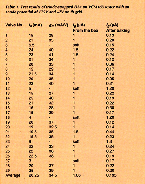
The results were disappointing. Five valves had very low emission, and the remainder passed a microamp or more of gas current. Worse, many valves exhibited unstable anode current. According to the date code on the envelope, namely 382, these NOS valves were made in 1982, so they were eighteen years old.
It seemed likely that the valves with very low emission failed due to manufacturing defects. The remaining valves were not quite acceptable, yet it seemed unlikely that they had gross defects, but more probable that the getter had failed to mop up leakage over the years.
Although operating the valves for a few hours might clear the residual gas, the anode current was unstable, and in that time, the fragile cathode would be bombarded, possibly reducing life expectancy.
I didnt want to risk damaging the new valves, so I decided to experiment on some expendable valves. The EFI84 RF pentode can barely be given away, so I repeated the tests with a mixed batch of twenty nine NOS EFI84 of differing ages and manufacturers. The results are summarised in Table 2.
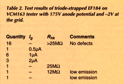
There are well known 'fixes' for low-emission and poor heater-to-cathode resistance that will be covered later in this article, but I now had ten valves with the same symptoms as the D3a that I could afford to destroy.
Since chemical reactions double their rate for every 10°C rise in temperature, perhaps the getter could be provoked into restoring the vacuum by heating the valves in an oven? Maximum envelope temperature is typically specified as 200°C, and domestic ovens are known to have erratic temperature control, so the gas oven was set to 'warm'.
Three hours later, the valves were removed and tested. Gratifyingly, there was a noticeable improvement, with all ten valves registering approximately half their previous gas current.
Clearly, the hypothesis was plausible, but the removal of gas seemed likely to be exponential. Reducing the residual gas and gas current to <1% of its original value would require more than 7 × 3 = 21 hours (27 = 128).= A cookery book that I consulted suggested that gas Mark 2 is around 130°C. As the oven temperature had previously been measured with a thermocouple probe as being around 100°C, this should give an eight-fold improvement without causing damage, and reduce the time required to 7 hours.
Although the AVO valve tester was capable of indicating the gas current and its improvement, it could not make an accurate measurement. So I made a break in its grid bias supply and substituted a Fluke 89 IV true RMS reading ammeter to enable a better reading. The true RMS reading DVM was necessary for comparison with the internal meter because valve testers test with half wave rectified AC, but gas current is read by a moving coil meter calibrated for DC.
All the D3a valves were added to the EF184, the oven was set to gas Mark 2 - later measured at 120°C - and the valves were left overnight for 13 hours. On removal, the valves were tested for gas current, and the results after baking were added to Table 1.
Although the gas current measurement before baking was necessarily somewhat inaccurate - 1μA on a 100μA FSD movement - the average improvement in gas current due to baking was a factor of five. While testing, I found that anode current and gm were noticeably lower for all valves, but stable. They now agreed closely with a known good valve, suggesting that the previously high, and unstable, characteristics were a direct consequence of the gas current.
Although they showed an improvement in gas current, the very soft valves remained low emission and were set aside.
Baking Tips
Valves that have no manufacturing defects, but have been in storage for many years may accumulate a little gas. It is possible to accelerate the getter and reduce gas current by a factor of five by heating the valve to 120°C in an oven for 12 hours, without any risk to the cathode.
Grid ionization current could easily be the dominant form of noise in high resistance circuits, such as condenser microphone head amplifiers. As a result, it makes sense to routinely bake valves intended for this type of use before selecting for low noise.
However, because surface contamination on the glass envelope of the valve produces leakage paths that can cause noise, it is usual to clean the envelope scrupulously, and subsequently only handle the valve with cotton gloves [3] Electrostatic cardioid microphone M7, BBC Technical Instructions (Recording), Instruction S.2 Section 5.3.. This process should be done before baking, otherwise it might not be possible to remove any hardened contamination.
Unfortunately, as a consequence of the baking, the painted lettering on the valve shows a little discolouration, appearing as if the valve has had a few hours use.
Other Valve Fixes
Although baking appears not to carry any risk of valve damage, the final two 'fixes' carry considerable risk...
Low Rhk
The consequences of low heater-to-cathode voltage depend greatly on the circuit and on Vhk. An EL34 output valve passing a cathode current of 70mA, with Vhk at +35V, and Rhk at 100kΩ will scarcely notice the extra 350μA leaking into the cathode. Any noise will be short-circuited by the cathode bypass capacitor.
Conversely, a cathode follower used in an active crossover requires a signal-to-noise ratio of at least 90dB. Although cathode resistance is low, it is not a short circuit. Worse, Vhk may well be elevated to 100V, so excellent Rhk is likely to be required.
Contamination causing poor Rhk can sometimes be burnt away on a valve tester. The tester is set to test Rhk with normal heater voltage and the cathode is allowed to warm to normal temperature. Heater-to-cathode resistance is then closely monitored and heater voltage is increased to 150%.
The resistance will fall, but if you are lucky, the rate of fall will slow - or even reverse. Assuming this effect occurs, immediately reduce the heater supply, and allow the valve to cool. The result should be an improved Rhk. Some valves cannot be recovered by this technique, and others may need repetition to make them acceptable, but the success rate is quite high.
The risk is that by deliberately over-heating the cathode, some of the emissive surface may be evaporated and deposited onto the nearby grid. The grid now has its own emissive surface, and if the valve is operated close to maximum anode dissipation, it may become warm enough to emit electrons, causing thermal runaway, leading to the valve's ultimate destruction.
Low Emission Due to Cathode Poisoning
Valves that have been operated for a long time at very low anode currents are likely to develop a cathode interface resistance that effectively limits electron emission, but the 'fix' is violent.
The valve is heated with 150% heater volts, anode voltage is set to a slightly higher than normal value, and Vgk is adjusted until enough electrons are dragged from the cathode that the anode glows deep cherry red. The valve is left to fry for perhaps five seconds, before all voltages are removed.
With a bit of luck, the control grid has not been covered in evaporated cathode material. When tested a few minutes later, the valve might show better emission.
Rejuvenation carries a very high risk, and the results are not generally very good, so the process is only really worthwhile on picture valves. Dedicated television tube rejuvenators have been made, but the risk of destroying the tube is high. Nevertheless, tube replacement is expensive, so rejuvenation may be considered to carry an acceptable risk.
References
- Principles of electron tubes, pp. 112, 123, J W Gewartowski & H A Watson. 1965 Van Nostrand. Princeton. New Jersey.
- Valve Amplifiers, Morgan Jones, 2nd Ed. 0-7506-4425-7.
- Electrostatic cardioid microphone M7, BBC Technical Instructions (Recording), Instruction S.2 Section 5.3.
|