|
I found this article whilst researching the 6JH8. It is another example of the Simplex Stereo principle. Also this article.
I've been fascinated with beam deflection tubes (also known as sheet beam tubes) ever since I first discovered them in the RCA Receiving Tube Manual. I used one to build a reflexed superhet receiver which was discussed by Joe Sousa in this post. There was also a brief mention made, in that discussion, of the common mode/differential mode simplex technique used in early CBS stereo amplifiers.
One evening, with some spare time on my hands, I concocted a rather curious one tube audio amplifier using a 6JH8 sheet beam tube. I tinkered with it in my spare time for a couple of weeks before finalizing the circuit as shown below.
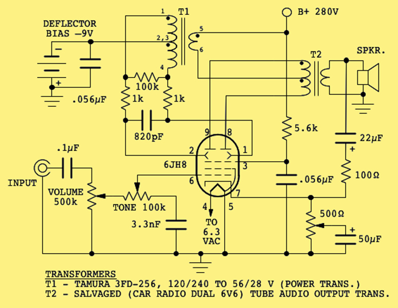
The full circuit.
It reflexes the signal using the same common/differential mode technique previously discussed. The input is a line level audio signal which passes through the volume control and simple tone circuit, to the 6JH8 grid. The signal is amplified and appears as a common mode signal at the two plates, passes through the primary of the output transformer and then to the primary of the interstage transformer. (This signal has no effect at the secondary of the output transformer because, being a common mode signal, it cancels out in the the primary winding.)
The secondary of the interstage transformer provides a differential audio signal to drive the 6JH8 deflection plates. Deflector plate bias of -9V is provided by a battery connected to the interstage transformer centre-tap. The battery provides no actual current, and therefore should last for its normal shelf life. In fact, charge accumulation on the deflector plates will cause a negative current flow which would have the effect of charging the battery.
The differential signal on the deflection plates causes the electron beam to swing between the plates, producing a differential (i.e., push-pull) plate signal which drives the output transformer and the speaker.
The circuit was constructed breadboard style, on a small piece of plywood as shown below:
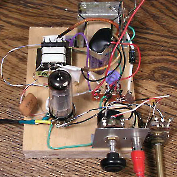
The prototype amplifier.
Of course, there are many design compromises made here. Most notably, the total plate current is controlled by input signal applied to the grid. Hence, positive excursions will increase the total plate current while negative excursions will decrease it. As a result, the final differential signal at the plates will be slightly asymmetrical, causing some distortion. Choosing a quiescent operating point at a fairly high current level helps to reduce the effect, as does the voltage magnification effect of the interstage transformer. Further correction is provided using negative feedback from the output back to the cathode.
Further compromises are due to the limited selection of components I had available. The output transformer is from an old car radio which used push-pull 6V6 tubes and drove an 8 ohm speaker. In the present circuit, a 4 Ω speaker is a better match with this transformer. The interstage transformer is actually a small power transformer with 120/240 Volt primary, and 56/28 volt secondary. It works surprisingly well. However, when unloaded it has a severe resonance at about 500Hz. Adding the network consisting of the 100 kΩ and 1 kΩ resistors, and the 820 pF capacitor damped this out. The negative feedback also flattened out the response. Using a scope and an audio generator, I measured the ±3 dB frequency response to be from less than 100 Hz to about 10 kHz when driving a 4Ω load.
Optimum anode voltage is about 280 Volts. Lower plate voltages reduce the output power, but above 280 Volts, there is no significant improvement. The 500 Ω potentiometer in the cathode circuit sets circuit gain by adjusting the amount of un-bypassed resistance. I found the best operating point to be when the un-bypassed cathode resistance is about 50 Ω.
It has been a while since I made output power measurements, and I didn't take very good notes at the time. But if memory serves me, it is capable of delivering a couple of Watts into a 4Ω load, which is surprisingly good for a non-power tube. I must say that I was pleasantly surprised by the audio quality from such a non-standard circuit, although I don't think I would recommend it to audiophiles.
|