|
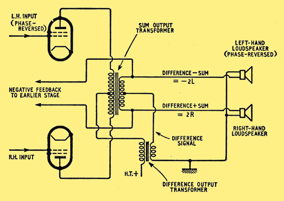
Phantom working has long been known to line engineers: the basic principle is that a balanced two-wire circuit can carry an additional unbalanced circuit between the two lines and earth, or a pair of two-wire circuits can carry an additional balanced circuit between the two pairs. The former condition corresponds to a Class A push-pull amplifier without a phase-splitter; that is, a push-pull signal could be fed in and extracted, amplified, in the normal way. Another signal, this time unbalanced (i.e., one side earthed), could be fed to both input stages in phase and extracted from a second output transformer in series with the HT feed to the centre-tap of the push-pull output transformer: for this signal the amplifier operates as two paralleled single-ended amplifiers.
This system is used to provide two amplifiers for the price of one in the American Columbia Broadcasting Systems range of stereophonic gramophones. Naturally, the distortion for the same power output is higher in the paralleled or phantom channel than in the push- pull channel and this means that it would be unwise to feed nearly identical signals to both phantom and normal inputs. If, however, the sum signal is fed into the push-pull channel and the difference signal is fed into the phantom channel the distortion produced should be acceptable because the power required for the difference signal should be less than that required for the sum. The outputs from the amplifier can be reconstituted into left and right signals by appropriate inter-connection of the secondaries of the output transformers.
Another interesting feature of the system is that no input-matrixing arrangements are necessary to produce the sum-and-difference signals provided that left-hand and right-hand inputs, one phase-reversed, are available. This means that a four-terminal stereo pickup can be used, the connections to one generator being reversed from the normal in-phase output condition (pickups with three terminals are suitable if out of phase outputs are provided). One loudspeaker, too, must have its connections reversed to restore correct phasing.
References
- A Two-Way Stereophonic Amplifier by B B Bauer, J Hollywood and G Maerkle, Audio, October 1958.
- Bi-Ortho Output Circuit. C Nicholas Pryor, Audio, November, 1958.
- The Stereoplex
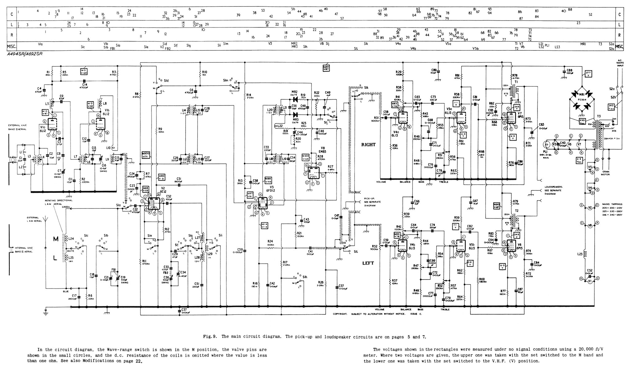
- Simplex Stereo in the Murphy A674SR Radiogram. The circuit diagram of the MkI can be found here and the MkII here.
- Simplex Stereo Re-Visited, A C Wyatt BSc FIP3, April, 2020.
|