|
A new line of miniature battery tubes, including a converter, a radio frequency amplifier, a diode-pentode and a power output pentode has been made available. These new tubes are designed to operate efficiently on a 45-volt supply with the filament operating directly from a single dry cell. The tubes are about two inches long and less than three quarters of an inch in diameter.
A feature of this new line of tubes is a decrease in size without an increase in cost. This is accomplished by using a simplified envelope design which in the majority of cases permits standard size electrodes to be assembled using conventional manufacturing procedure. A new button stem in which the external leads serve as base connections contributes materially to the reduction in tube dimensions.
The small size and efficient operating characteristics of the new miniature tubes make them especially applicable to compact communication equipment as well as portable broadcast receivers. Also they may find application in special fields such as hearing aids, meteorological service, or other places where size and weight are a consideration.
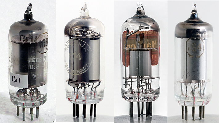
The first B7G based valves as discussed in this paper.
The trend in radio receiver design, during the past two years has been toward small, low-priced models. This, together with the increasing popularity of portable, self-contained, battery receivers, has created a demand for smaller and less expensive radio tubes. The new miniature tubes, with their simplified construction and great reduction in size, provide a logical answer to this demand.
Although several types of small tubes are now available, these, in general, use very small parts with close electrode spacing requiring slow, careful, assembly by highly skilled operators and special fabricating processes. Such tubes have application wherever the requirement for special characteristics warrant their increased cost. However, the inherently higher cost of producing tubes of this character is sufficient to prohibit their general use in popular-priced broadcast receivers. Consequently, the problem of obtaining a small, low-cost tube depends for its solution upon the selection of a satisfactory design of simplified construction which will not only after the desired reduction in size, but also lend itself to usual manufacturing operations.
In the design of this new line of tubes every effort has been directed toward producing the smallest glass tubes which can feasibly be manufactured by present high-speed methods of fabrication. The variations required in manufacturing technique have, therefore, been carefully restricted to procedures which have been proven by prior experience.
In so far as possible, all parts and materials which serve no functional purpose in the completed tube have been eliminated.
The new miniature line consists of four tubes, the RCA-1R5, converter; RCA-1T4, radio-frequency pentode; RCA-1S5, diode-pentode; and RCA-1S4, power-output pentode; and provides a complete complement for receiver design. All of the tubes operate efficiently from a small, 45-volt battery and their filaments are designed for operation at 50 mA (except the RCA-1S4 which requires 100 mA) supplied directly from a single dry-cell.
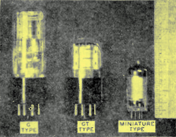
Fig. 1 - New Miniature Tube compared with smallest present equivalent types.
The reduction in tube dimensions accomplished by the new design is illustrated by the photograph, Fig. 1, in which a miniature tube is compared with a G-type and a GT-type having similar characteristics. It is interesting to note that the miniature tube is about two inches long and less than 0.75 inch in diameter and only displaces about 20 per cent of the receiver space required by the GT-type equivalent. This large reduction in volume should recommend these new tubes for those applications where compactness is essential. They should be especially desirable in the design of portable broadcast receivers, pocket receivers and police equipment. They may prove useful in meteorological work, hearing-aid and other special applications where size, weight and cost must be considered.
The manner in which the reduction in size has been effected together with the various special features of design and manufacturing technique employed in the production of the new miniature tubes are discussed in the ensuing paragraphs.
Stem Design
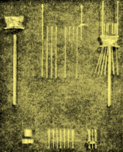
Fig. 2 (Top) - Parts and an assembled unit of a conventional stem. (Bottom) - Miniature button stem and component parts.
In Fig. 2 (top) the various parts and an assembled unit of a conventional-type stem are shown, In this stem, the electrode leads are located in a single plane through the centre of the preformed flare and the vacuum seal is made by pinch-pressing the molten glass onto the short sections of special seal wire. The particular stem shown in Figure 2 (top) is representative of one of the shortest stems in general use. In this case the length of the glass flare from the sealing line to the top of the press is approximately 14 mm (0.55 inch). To this value must be added sufficient length to provide for trimming and forming the leads and making the welds of the leads to the tube electrodes. This additional length of approximately 10 mm (0.39 inch) makes the total distance from the point of sealing to the lower edge of the mount approximately 24 mm (0.94 inch), It will be evident that this long length is non-essential to the electrical characteristics, but results from the mechanical limitations of this type of stem design. The stem length has been greatly reduced in the design of the miniature button stem by making the sealing position to the enclosure coincident with the vacuum seal line as shown in Fig. 2 (bottom). The distance from the sealing line to the lower edge of the mount has by this construction been reduced by 65% and results in shortening the overall length of the finished tube by 14 to 15 mm (0.55 to 0.59 inch).
The use of the button type stem also contributes to a reduction in tube diameter. The conventional-type stem shown in Fig. 2 (top) requires a flange diameter which exceeds the width of the stem press. In the GT-type tube of Fig. 3, the flange diameter is approximately 1 inch and a bulb diameter of 1.125 inches is, therefore, required for successful assembly. In comparison, the miniature type has seven leads located on a 0.375 inch circle in a glass button only 0.6 inch in diameter. This stem can be sealed into a bulb having an outside dimension of approximately 0.69 inch.
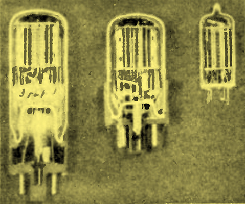
Fig. 3 - Cut-away view of G-Type (left), GT-Type (centre), and Miniature Type (right).
Although the diameter of the tube is reduced, the lead spacing has been improved by use of the button-type stem. For example: seven leads sealed into a conventional-type stem cannot have an average spacing much in excess of 0.110 inch between leads. In the miniature tube design seven leads are spaced 45° apart on a circle 0.375 inch in diameter. Thus, the leads are spaced 0.147 inch apart, an increase of 33 per cent more than can be obtained by use of the larger conventional type stem. From this explanation, it is evident that in those instances where three or more leads are required, a much smaller diameter stem of the button type can be designed to have a greater lead spacing than would be possible with the conventional flat-press stem (Pinch). The wider spacing reduces the possibility of electrical leakage and minimizes capacitance coupling between leads.
It is evident that in addition to the reduction in size realized through the use of the miniature button stem that a considerable saving in materials has also been achieved by departing from the conventional pinch-press stem. For example: only about 20% of the amount of glass used by the small conventional type stems is required for the miniature stem. The glass does not need to be preformed, but is cut directly from tubing of the correct diameters to the short lengths required. All leads used in the miniature stem are identical regardless of tube type. Only three types of parts are required to produce the miniature stems as compared to six types of parts for the conventional stem. This standardization of parts is a decided advantage in manufacture.
Since the miniature stem was designed for fabrication on the same equipment and under the same technique employed for the production of metal-tube button stems, only slight modifications of existing equipment were required.
Bulb
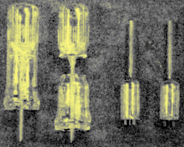
Fig. 4 - (Left Half) - Conventional type tube before and after sealing, with discarded collet. (Right Half ) - Miniature-type tube before and after sealing, with no collet.
The miniature bulb (shown as part of Fig. 4) is moulded from glass tubing and has no collet. This method of fabrication is economical in that no glass is wasted and close tolerances in the bulb and the stem combine to make sealing a relatively simple operation. The miniature stem has no tubulation and it is, therefore, necessary to provide an exhaust tubing in the bulb. This is done by reviving the bulb seal-off which was used by the incandescent lamp and radio tube industries for many years.
Mount
In the past, the designers of small tubes have concentrated upon obtaining a reduction in mount size by close electrode spacings and very small parts, the primary reason being to reduce inter-electrode capacity and lead inductance in order to improve high frequency operation. Tubes of this design are difficult and slow to assemble in the factory and must necessarily be expensive to produce. Examination of the three tubes shown in Fig. 3 will disclose that the mounts in all three types are identical for mount parts and electrode spacings except, in the case of the miniature, that the anode has been changed to a simple cylindrical sleeve so as to permit insertion into the bulb. In the miniature tube, the getter has been mounted above the top mica to eliminate any possibility of leakage across the stem due to getter. Maintenance of mount dimensions identical to those used on other types of receiving tubes, provides standardization of parts and materials and facilitates factory operations by permitting assembly on common fixtures and at usual mounting speeds.
Baseless Construction
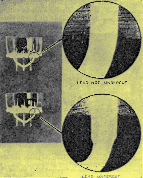
Fig. 5 b Photographs showing how undercutting leads of miniature stems protects the glass seal under extreme conditions of bending.
From a comparison of the tubes shown in Fig. 3, it will be apparent that the reduction in size of the miniature tubes has been obtained almost entirely from the stem and enclosure, either by redesign or elimination of parts. Some of these changes may be considered as elimination of safeguards previously considered essential to tube construction. For instance, the tubulated bulb used in early incandescent lamp and radio tube practice has been incorporated in the miniature design. The Bakelite base with is rigid pins for socket contacts separated by intermediate flexible connectors from the vacuum seal has been replaced by short pins sealed directly into the glass of the stem. Although laboratory tests have indicated that the glass seal is sufficiently strong to withstand the normal pressures which will be exerted on the base pins in various applications, it has been deemed advisable until experience can be obtained from the field to incorporate an additional safety factor of undercut pins as illustrated in Figure 5. This device consists of reducing the diameter of a short length of the pin at some point below the glass so that in case the lead is accidentally deflected from its normal position the bending will be localized in the weakened part of the pin and the vacuum seal will not be affected. If a solid lead is bent, the fulcrum point of the bend is located at the edge of the glass seal as is shown in Fig. 5 (top). This causes chipping of the glass and may result in a ruptured seal. An undercut pin which is similarly bent (Fig. 5 bottom) has absorbed the distortion entirely in the weakened section and has not disturbed the vacuum seal. The advantage of this artifice is that the strength of the contact pin can be reduced to well within the safe limits permitted by the strength of the glass seal. The amount of this lead under-cutting can be varied or eliminated entirely without altering the contact diameter of the pins.
This development provides a new line of small tubes having very efficient operating characteristics at low battery voltages. These tubes are designed especially for use in compact, lightweight, portable equipment.
The co-operative efforts of the many engineers involved in this development are recognized and appreciated, although it is impractical to acknowledge the contributions individually.
|