|
Some details of the UHF equipment.
Signalling Equipment No. 10 which forms part of the Army Wireless Set No. 10, was described under the title 'Pulse Width Modulation' in the June issue of Wireless World.
It was explained how eight audio-frequency channels were made to modulate in width a series of rectangular pulses in the pulser or sending section of the equipment and how the separator recovered the audio channels from the received width-modulated pulses.
The width modulated pulses produced by the pulser are used to modulate a magnetron UHF sender working at a frequency of about 4.5 GHz. The receiver is of the super-heterodyne type and the pulses in its output are passed to the separator section of the Signalling Equipment No. 10.
It is the purpose of the present article to conclude the account of the 10 set with a description of the UHF sender, receiver and aerial system.
It is usual in UHF equipment to conduct the energy from one unit to another by means of waveguides and coaxial cables. The principles of waveguide engineering and their uses in connection with coaxial cables have been dealt with in the issues of Wireless World for September and October, 1944. Resonant cavities are used in UHF equipment for tuning purposes in much the same way as the more familiar tuned circuits are employed at lower frequencies.
These cavities are described below in relation to this particular equipment, but it is as well to give some general remarks at this point. The same principles apply to them as to waveguides and it is assumed that reference has been made to the earlier Wireless World articles. A resonant cavity is merely a waveguide of a certain length, usually a multiple or sub-multiple of a wavelength, closed at each end. Where such a cavity is, say, one wavelength long and energy of the appropriate frequency is fed into it, this energy will build up until quite large amplitudes are obtained. It will then be seen that if a cavity is equipped with a movable piston at one end it fulfils much the same purpose as the more familiar tuned circuit consisting of coils and capacitors at lower frequencies. Arrangements for feeding in and abstracting energy from a resonant cavity are similar to those used for the waveguides treated in the earlier articles. The tuning cavities are of rectangular cross-section and are designed for electromagnetic waves of H01 mode. It will be remembered that for H01 waves longitudinal loops of magnetic lines of force are formed and electric lines of force stretch from one side of the enclosure to the other. In a resonant cavity, the loops build up to form standing waves, the amplitude reached de-pending on the power dissipated in the material of which the cavity is made and the load to which it is coupled.
The waveguides used in this equipment are of circular cross-section and propagate H1 waves. Longitudinal loops of magnetic lines of force are formed in this case also and the transfer of energy along the waveguide may be considered as due to the loops of magnetic lines of force moving down the waveguide.
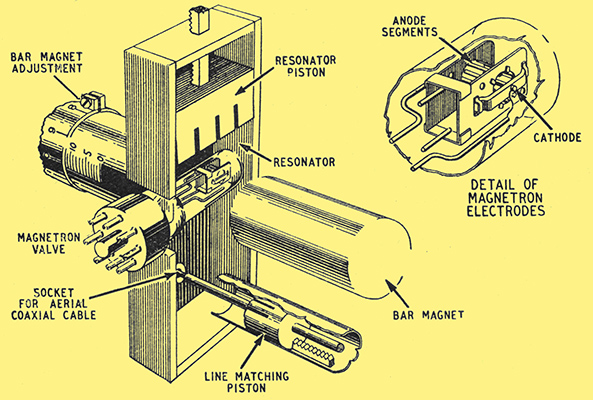
Fig. 1. This cut-away drawing shows the interior of the resonator used with the magnetron in the sender. The construction of the magnetron itself is indicated in the inset-sketch.
A frequency of about 4.5 GHz is generated by a split-anode magnetron valve. The use of the magnetron valve in this connection has been described elsewhere, but it is of interest to note the construction of the electrodes which is shown in the inset of Fig. 1. The anode segments are arranged in cylindrical formation, the cathode lying along the axis.
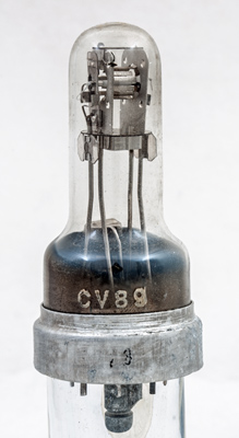
The CV89 magnetron used in the No. 10 Set.
The magnetic field required to give the necessary spiral motion to the electrons is supplied by two cylindrical bar magnets and the magnetron mounting allows the valve to be rotated to a certain extent to bring the axis of the cylindrical anode parallel with the field. One of the magnets has a micrometer adjustment which enables the strength of the magnetic field to be varied, to suit the particular type of valve employed.
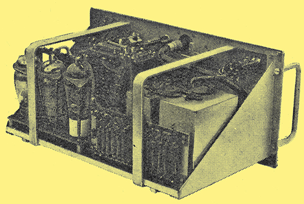
The sender has its own built-in power supply unit.
Energy is extracted from the magnetron by arranging that it lies in a rectangular cavity. This cavity is tuned to resonance at the frequency of the oscillator by an adjustable piston. The central conductor of a coaxial line crosses the cavity at a distance approximately one-quarter wavelength from the end and this picks up energy which is conveyed by the coaxial line to the aerial system. The impedance of the coaxial line is matched by an adjustable piston in a cavity into which the centre conductor extends on the side of the resonator opposite the point where the coaxial line enters.
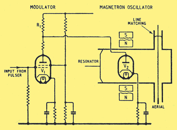
Fig. 2. Circuit diagram of the sender including the modulator valve which is fed with the pulses produced in the pulser unit.
The manner in which the magnetron is modulated may be understood from the circuit of the sender shown in Fig. 2. V2 represents the oscillator and V1 the modulator. With no input from the Signalling Equipment No. 10, V1 is so biased that it draws current. The magnetron HT supply is taken from a voltage-dropping resistance R2 common to both valves and when V1 is taking current, the anode potential of V2 is too low for that valve to oscillate. The arrival of a negative pulse from the Signalling Equipment No. 10 at the grid of V1, however, stops that valve from drawing anode current and the consequent rise in the anode voltage of V2, about 300 V, is sufficient to start the magnetron oscillating.
The output of the Signalling Equipment No. 10 consists of a series of negative-going pulses and thus the output from the sender consists of corresponding pulses of UHF energy.
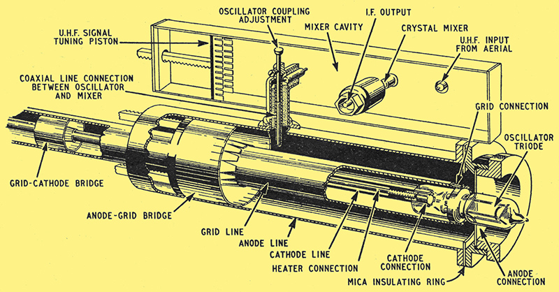
Fig. 3. Construction of oscillator and mixer used in the receiver is shown here. The oscillator is a CV90 triode and the third harmonic of its output is fed to the crystal mixer.
At the receiver (Fig. 3), the input from the aerial is fed into a mixer cavity or resonator, from a coaxial cable, the centre conductor projecting into the cavity about ¼ wavelength from one end. Energy from a local oscillator is similarly fed into the cavity at the other end. A crystal detector mounted across the cavity, i.e., parallel to the direction of the electric field, rectifies the oscillator and signal frequencies, thus producing a difference frequency (i.e., signal frequency minus oscillator frequency) of about 45 MHz which is amplified by an IF amplifier. It will be seen that there is nothing fundamentally different between this circuit and that of an ordinary superheterodyne receiver.
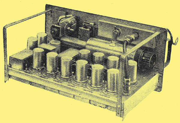
Interior view of the receiver. The tuner is just visible close to the panel. The majority of the valves are ARP35's.
The signal frequency is tuned by a resonating cavity instead of the more familiar coil and capacitor. It is also interesting to notice that the principle of heterodyning applies also at these frequencies although the arrangements required to carry it out are somewhat different.
The local oscillator uses a miniature-type triode valve oscillating at about 1.485 GHz. The third harmonic of this frequency is used to mix with the signal frequency. The arrangement of the oscillator itself is very similar to that of the familiar triode oscillator tuned by a Lecher- wire system, the difference in this case being that the wires are replaced by concentric cylinders. Such an arrangement constitutes a system of concentric lines which are tuned by movable pistons, the pistons being the analogue of the movable bridges used with Lecher-wire tuning. For this reason they are referred to as bridges in Fig. 3. The necessary feedback between the anode-grid lines and the grid-cathode lines to cause the circuit to oscillate is provided by internal capacitance in the valve. The coupling between the mixer cavity and the cavity between the anode and grid lines is by means of a concentric feeder, the centre conductor extending into the mixer and oscillator cavities at each end. The oscillator coupling adjustment shown in Fig. 3, by varying the extent to which the centre conductor can protrude into the oscillator cavity, varies the amount of coupling between the oscillator and the mixer cavity.
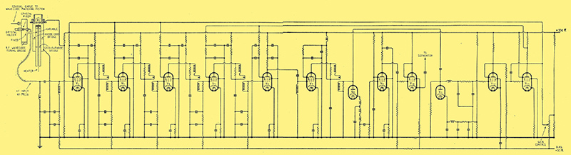
Fig. 4. Circuit of the receiver. The mixer is followed by a wide-band IF amplifier with diode detector and a VF stage. The output pulses are fed to the separator.
The IF amplifier (V2-V7 in Fig. 4) is of conventional design and similar to the television amplifiers met with in commercial television receivers. A low-capacitance diode V8 acts as detector and this is followed by an amplifier V9 and a cathode-follower stage V10, the latter giving a low impedance output required. to match the input of the Signalling Equipment No. 10. This output consists of a series of positive-going pulses. Automatic gain control is provided by the diode V11, which rectifies part of the output of the IF amplifier, followed by the DC amplifiers V12 and V13. The control is applied direct to the screens of the first three IF valves from the anode of V13.
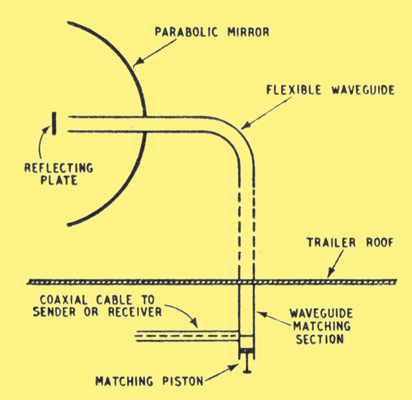
Fig. 5. This sketch shows the arrangement of the aerial system. A paraboloid is energized by a waveguide having a reflector plate opposite to its open end.
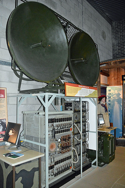
The aerial system which is illustrated diagrammatically in Fig. 5, comprises two parabolic mirrors, one for the receiver and one for the sender. These aerials are mounted on the roof of a trailer, the remainder of the equipment being inside. The connection between each aerial and its sender or receiver is in two stages. A flexible waveguide connects the mirror to a waveguide matching section just below the trailer roof and a coaxial cable connects the matching section to the sender or receiver. The waveguide enters the centre of the mirror at the rear and carries a circular reflecting plate in front of its open end. This reflecting plate lies in the focal plane of the mirror Inside the trailer the waveguide terminates in a matching section. This consists of a rigid tube connected at one end to the flexible guide and closed at the other by a movable matching piston. The centre line of a coaxial cable crosses the tube in front of the piston which can be adjusted to give the correct impedance match.
This article is published by permission of the Director General of Scientific Research (Defence).
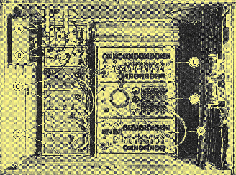
An interior view of the trailer of the No. 10 station. The various units are: A, waveguide matching sections; B, duplicate sender units; C, duplicate receivers; D, duplicate power supply units. The Signalling Equipment No. 100 consists of the pulser E, the monitor F, and - the separator G.
See also Details extracted from: WW2 British Army Battlefield Wireless Communications Equipment by Anthony C Davies.
| 
