|
Details of Army Wireless Station No. 10.
A brief account of the operational use of the No. 10 set appeared in the December issue of Wireless World, and another article described the principles of pulse-width modulation. Details are now available of the Signalling Equipment No. 10, the units in the 10 set which produce and demodulate width-modulated pulses. These pulses, once produced, are used to modulate in turn an ultra-high-frequency transmitter working in the 6-7[k[cm band. At the receiving end the width-modulated pulses appear in the output of the receiver and are then demodulated by the Signalling Equipment No. I0. The equipment is divided into two main units - the pulser and the separator.
The chief details of the circuit of the pulses are given in Fig. 3. Before discussing this, however, it may be as well to explain briefly the object of the apparatus. Narrow pulses recurrent at 9 kHz are width-modulated by the AF signals which are to be transmitted. The pulses are narrow with an average duration of 3.5 μsec. Each of the eight speech channels modulates a separate train of pulses of the same recurrence frequency, but all the trains are staggered in time so that they can fit together without interference. A synchronizing pulse is also included to control the receiving apparatus which sorts out the pulses, demodulates them and routes the AF signals to the proper output circuits.
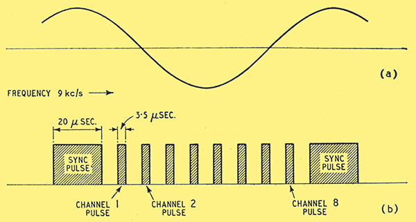
Fig. 1. The sine wave used to control the pulse generation is shown at (a) and the complete pulse sequence produced from it at (b).
The pulse starts with a 9 Hz oscillator of sine waveform. Its output takes the form shown in Fig. 1(a). From this oscillator is derived a sequence of rectangular pulses which are repeated for every cycle of the 9 kHz oscillator. This sequence consists of a synchronizing pulse followed by eight 'channel' pulses and they may be represented as in Fig. 1 (b).
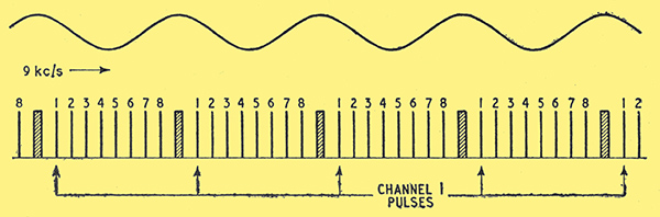
Fig. 2. This diagram shows essentially the same waves asFig. 1, but to a reduced scale so that several cycles of the wave can be seen. Pulses numbered '1' convey intelligence for channel 1, '2' for channel 2 and so on.
The channel pulses are so-called because each one is width-modulated by one of the telephone lines coming into the station and thus provides a 'channel' for conveying intelligence. The idea is easier to grasp from Fig. 2, which is Fig. 1(a) and (b) combined and reduced in scale. Here a number of pulse sequences is shown, and it will be seen that all the pulses marked '1' can be grouped to form a series of width-modulated pulses comprising the intelligence conveyed on channel 1, all those marked '2' can carry the intelligence conveyed on channel 2, and so on. It is by this system of interleaving pulses that a number of channels can be made to modulate a UHF transmitter.
The method by which the various AF channels are recovered from these pulse sequences in the receiving part of the Signalling Equipment No. 10 is described later in this article. This operation is performed by the b'separator'. It is best at this point, however, to look at the pulser circuits in more detail.
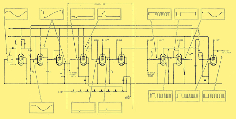
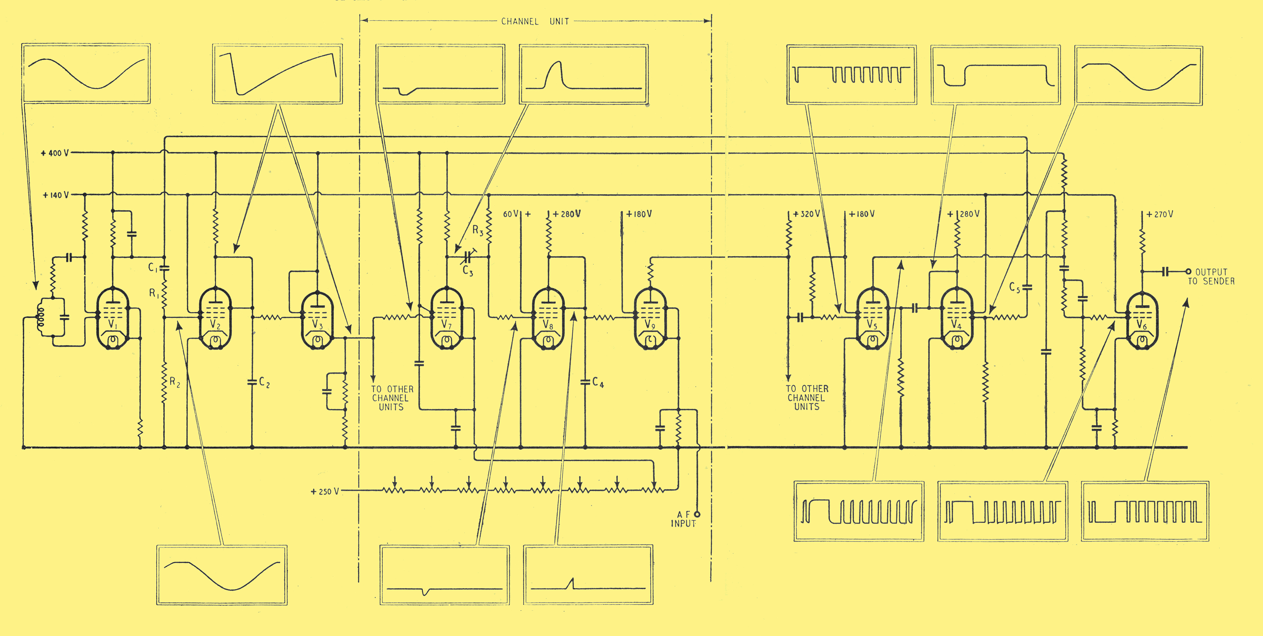
Fig. 3. The circuit diagram of the pulses, simplified by the omission of non-essential components such as test points. The wave forms at important points are indicated by miniature graphs enclosed in rectangles. The portion of the equipment between the vertical dash lines is repeated for each channel. As they are all identical only one of the eight is shown.
Fig. 3 shows the circuit of the pulser. The inset rectangles show the shape of the wave-forms at particular points in the circuit. so that the way in which the final pulses are built up can be seen. They should be referred to as each stage in the circuit is described.
The 9 kHz pulse-recurrence frequency, as it is termed, is generated by V1. It is a normal type of electron-coupled Hartley oscillator - the output being taken from the anode. This provides a certain buffering effect between the oscillator and later stages.
The saw-tooth generator is V2 in which C1, R1, and R2 have a time constant large compared with the period of 9 kHz oscillator; therefore C1 acquires a mean charge from the grid current of V2. The grid of V2 is consequently biased so that it only conducts on the peaks of the oscillation supplied by V1. When V2 is non-conducting, the anode circuit capacitance C2 is charged by the HT supply through the anode resistance. Before it has time to become completely charged, however, V2 takes current and C2 is rapidly discharged through the conducting path provided by the valve.
This process is continually repeated and thus a saw-tooth voltage is generated which is applied to the cathode-follower stage V3. This acts as a buffer and its output is distributed to eight channel units, each dealing with the input from one telephone line. We will deal with the channel unit concerned with channel 1, which is the only one shown in Fig. 3. The saw-tooth voltage in the output of V3 is applied to the grid of the first valve V7 in the channel unit. The action of the circuit can best be understood by considering what happens when the sawtooth voltage gradually rises from its lowest potential.
The cathode of V7 is given a positive bias so that the valve will not conduct at first. As the saw-tooth voltage on the grid becomes increasingly positive, however, a point is reached where the grid is more positive than the cathode and the valve suddenly conducts. This produces a steep fall in the potential of the anode and consequently in the potential of the junction between C3 and R3. The latter potential will however, rapidly recover, the time taken to do so depending on the time constant of C3 and R3. Thus a negative-going pulse is transmitted to the grid of V8.
It should be noted that the initial part of the pulse shown as the anode waveform of V7 is positive-going. This is , the recovery from the saw-tooth flyback and remains the same for all channel units. In other units the voltage remains constant between the end of this rise and the start of the fall when V7 becomes conductive. This interval depends on the bias on V7 and the greater the bias the more the voltage fall is delayed and the later the pulse on the grid of V8.
The grids of V7 on the remaining seven channels are each biased positively, the bias increasing progressively on each channel. The application of the saw-tooth to all the channel units, therefore, results in a series of successive negative-going pulses, one at the grid of each valve V8. This latter valve constitutes a saw-tooth generator. Its grid is biased positively so that normally the valve is taking current. The application of the negative pulse to the grid, however, stops the current for a short time. During this time the capacitance C4, which is normally short-circuited through the conducting path provided by V8, is charged by the HT supply. Before it has time to become fully charged the valve V8 conducts again and the capacitance is very rapidly discharged. Due to this action a saw-tooth voltage is applied to the grid of V9. This is the modulator and AF from the line corresponding to channel 1 is applied to its cathode. This valve produces width-modulated pulses of approximately rectangular shape at its anode.
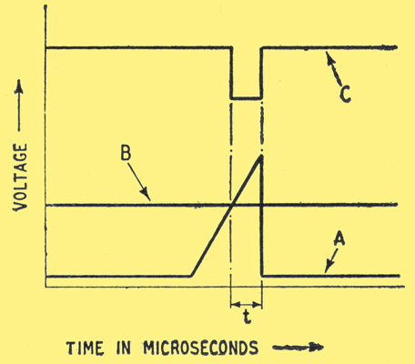
Fig. 4. The saw-tooth voltage on the grid of V9 is shown at A, the cathode bias at B, and the pulse produced at the anode at C. The width of the pulse depends on the magnitude of B.
In Fig. 4, A represents a saw-tooth voltage pulse on the grid of V9. In the unmodulated state the cathode is given a certain positive bias represented by B in Fig. 4. It will be seen that the valve will only conduct during a certain time t when the voltage between grid and cathode is more than that required to cut off the anode current and thus a pulse is produced at the anode, of width t This is represented by C in Fig. 4.
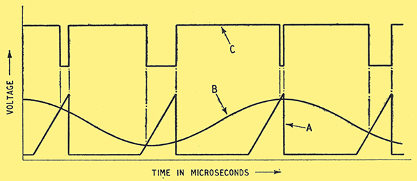
Fig. 5. This diagram illustrates the action of V9 with an AF signal applied to its cathode. The cathode bias B varies with the signal and so the pulse width varies as shown by C.
When a modulating voltage is applied to the cathode the line B has the appearance shown in Fig. 5, and as a consequence the pulses at the anode vary in width. Since the trailing edge of the saw-tooth is vertical it is the leading edges of the pulses which are modulated.
The output of V9, in common with that of similar valves in the other channel units, is fed to the grid of V5, a synchronizing pulse being applied to the suppressor.
The synchronizing pulse is produced by the valve V5, the grid of which is fed with the 9 kHz recurrence frequency from V1. The grid circuit is similar to that of V2, i.e. the, grid having a negative potential so that the valve will only conduct on the peaks of the 9 kHz sine wave. This produces negative-going pulses at the anode of V4 and the valve is biased so that these are of 20 μS duration. This pulse occurs on the peak of the recurrence frequency and the channel pulses occur during the rest of the cycle. Consequently the output of V5 consists of the synchronizing pulse followed by the eight channel pulses.
This series of positive-going pulses at the anode of V5 is fed to V6 which amplifies and squares the pulses and passes them to the UHF sender. The output from V6 will, of course, be negative-going pulses since the grid is fed with positive-going pulses.
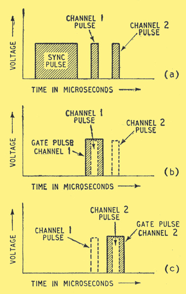
Fig. 7. The synchronizing pulse is shown at (a) followed by two channel pulses. It generates a series of gating pulses which permit channel pulses to pass only when channel and gating pulses are coincident. The two are shown at (b) for channel 1 and at (c) for channel 2.
At the receiving end the pulses corresponding to individual channels have to be separated from their fellows, demodulated and the resultant AF passed to the appropriate telephone line. This is done by a system of gating pulses. Fig. 7(a) represents the synchronizing pulse followed by two of the channel pulses.
These pulses are all applied to individual units, one for channel 1, one for channel 2, etc. The arrival of the synchronizing pulse causes gate pulses to be generated at certain intervals. The gate pulse is of longer duration than a fully-modulated channel pulse. That for channel 1 occurs at about the same time as the channel 1 pulse itself and similarly for channel 2, etc. Each channel unit will only admit a channel pulse during the brief period when a gate pulse is applied to it. Thus in the case of channel 1 unit, although all the channel pulses are applied to it in succession only the channel 1 pulse will be accepted since the gate is only open for long enough to allow the channel 1 pulse to go through (Fig. 7 (b) ). Immediately it has passed, the gate pulse ends and the unit is barred from accepting any more pulses until the next channel 1 pulse arrives. In the same way, immediately channel 1 gate is closed, channel 2 gate opens and admits the channel 2 pulse into the channel 2 unit and so on for the remainder of the eight channels (Fig. 7 (c)).
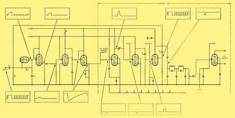
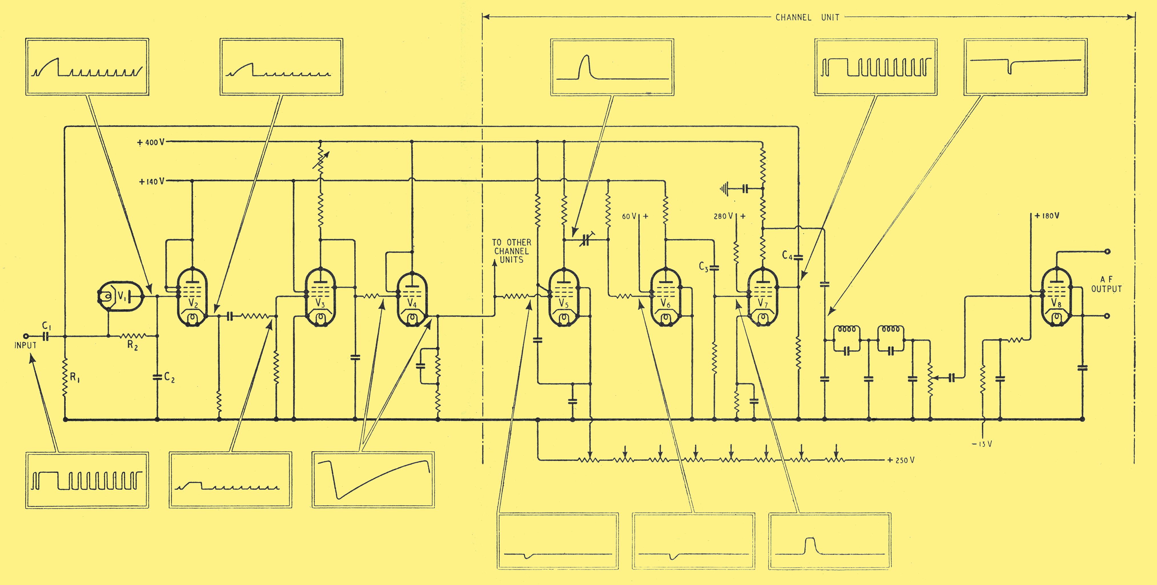
Fig. 6. The circuit diagram of the separator which, by generating gating pulses, separates the channel pulses and develops the AF outputs correctly routed to the proper output lines. V1 is an integrator to separate the sync pulse which controls the saw-tooth generator V3. Equipment to the right of the dash line is provided for each of the eight channels.
The output of the UHF receiver is in the form of positive-going pulses corresponding to the negative-going pulses produced by the pulser unit. These are fed to the diode V1 in the separator unit (Fig. 6). The time constant of C1 and R1 is long compared with that of the pulses so that the potential of the junction between C1 and R1 follows that of the incoming pulses. On receipt of a pulse the cathode of V1 is made more positive than the anode and the valve does not conduct. Therefore C2 commences charging but does not have time to become fully charged before the end of the pulse has arrived. At this time C2 discharges rapidly through the valve, the anode of which is now more positive than the cathode. The synchronizing pulse, being longer than the channel pulses, gives C2 an opportunity to charge to a higher potential than the shorter channel pulses. Thus a series of saw-tooth pulses is passed to V2 the pulse arising from the synchronizing pulse being of much higher amplitude than the following channel pulses.
A cathode-follower buffer-stage V2 is interposed between V1 and V3 because the grid circuit of V3 takes current and would, therefore, interfere with the operation of V1 if it were connected directly to it. V3 is a saw-tooth generator and operates in a similar manner to V2 in the pulser unit. The saw-tooth is triggered off by the synchronizing pulse (which rises to a higher potential than the main channel pulses) in the same way that the crest of the 9 kHz oscillator V1 triggers the saw-tooth generator V2 in the pulser unit. The grid current produces a bias sufficiently large for the channel pulses to have no effect. The output from V3 is applied to a cathode-follower V4 which operates in a similar manner to V3 in the pulser. From V4 the saw-tooth is distributed to eight separator channel units. We,will deal with the separator channel unit concerned with channel 1.
The circuit of V5 works in the same way as V7 in the pulser channel unit and produces a negative-going pulse at the grid of V6. The constants of the circuits are so chosen that this pulse is about 8 μS in duration. By a system of biasing similar to that used in the pulser channel units it is arranged that the V5 valves in the eight channel units produce their pulses in uniform succession following the reception by the separator of the synchronizing pulse. These pulses occur about the same time, relative to the synchronizing pulse, as the original channel pulses.
Reverting to channel 1, the valve V6 produces at its anode a sharp positive pulse also of about 8 μS duration. This comes about because the grid pulse is steep and the anode voltage is comparatively low. This is the gate pulse and is wide enough for the corresponding modulated pulse (3.5 μS ±2.33 μS) to fit inside. The gate pulse is applied to the control grid of the gate valve V7 and the train of pulses from the UHF receiver, to the suppressor grid. The control grid is normally biased so that the valve will not conduct. It reaches this condition after the first few gate pulses pass when the set is started up - the pulses causing the valve to draw grid current which charges up C3 and thereafter keeps the grid negative. After this state has been reached however, a gate pulse will remove the bias for a certain time, until C3 becomes charged again, and this would in the normal course of events enable the valve to conduct. A similar biasing effect is associated with the suppressor grid of V7, the capacitor responsible being C4. Thus, unless a pulse is present at both grids, the valve will not conduct, but when two pulses are present at the same time it will conduct for the duration of the shorter pulse only. The V7 (channel 1) will therefore pass the channel pulse associated with channel 1 since the gate pulse is only present on that particular valve for just sufficient time to allow the valve to conduct for the duration of the channel 1 pulse.
Similarly V7 of channel 2 will 'capture' the channel pulse associated with channel 2 and so on for the other channels. The output from each V7 anode is thus a series of negative-going width-modulated pulses. On passing these through a suitable AF low-pass filter (cut-off 4 kHz) the modulation frequencies are recovered and amplified by V8 before being passed to the appropriate telephone line.
|