|
Some pitfalls in applying it to quality amplifiers.
The behaviour of a valve circuit is radically affected by feeding back part of the output voltage into the input circuit. This has been done for some considerable time past, with and without intention. De Forest was not long in applying positive feedback to his three electrode Audion valve to obtain a detector of high sensitivity, or an oscillator. Negative feedback was also used even in the infancy of radio (multi-stage amplifiers of the First World War embodied this feature), but it was Nyquist's work which ten years ago paved the way to a deeper understanding and hence more widespread application of all forms of feedback [1] Regeneration Theory, H Nyquist: Bell System Technical Journak, Jan., 1932..
Since then it is usually held that the performance (especially the frequency/gain characteristic) of an audio amplifier is enhanced by the provision of negative feedback. This belief is based on the usual analysis [2] Radio Engineering, 2nd edition, F E Terman, or Communication Engineering, 2nd Edition, W L Everitt, p. 463, etc. of negative feedback which assumes that in the absence of feedback the output voltage contains a distortion term D which is independent of the gain m. It is then easily shown that with a fraction β of the output voltage Vo fed back in any phase whatever, both gain and distortion are modified in the ratio 1/(1 - mβ). In general, of course, mβ is a complex term and a function of frequency. The feedback is said to be purely negative if mβ = - |mβ|, where |mβ| is the magnitude (positive) of, the now purely negative mβ. In these circumstances, it follows that 1/(1 - mβ) = 1/(1 - |mβ|) a factor less than 1 by which both D and m are reduced.
Now there is no point in comparing an indifferent amplifier with a better one unless. both have the same gain other things being equal, this could only be realised by suitably increasing the load or number of stages of the amplifier containing negative feedback. In other words, the comparison must be on the basis of a given output for a given input, i.e., on the basis of a given amplification factor. Doubt may then arise as to whether negative feedback is of any use; for the necessary addition of extra loading or stages tends to add equally to both the amplification and the distortion. The argument is admittedly somewhat academic, as any telephone engineer may proudly point to his amplifier racks containing dozens of valves, an achievement unthinkable without the bounties of negative feedback. Nevertheless, this does not solve the problem and it still awaits a general solution.
The difficulty lies in the varied sources of the distortion term D which it is rather rash, if expedient, to assume independent of the output voltage proper. This could at best be maintained about one of its parts, e.g., mains hum, possibly about valve noise, certainly not about distortions arising in the grid circuit (grid current), in the mutual characteristic (bottom bend curvature) or in the anode circuit (non-linear behaviour of anode resistance RA and load impedance ZL, the latter also varying in general with frequency). Only one factor has been cleared up so far, i.e., irregularities arising from changes in the amplification factor of individual valves, due to arbitrary reasons [3] Reducing Variations in Amplification by Means of Negative Feedback, J Peters, Hochfrequenztechmk u. Electroakustik, p. 46, Feb., 1942 (in German).. Peters has shown that the greatest improvement obtains when the stage or stages over which feedback is applied has a gain equal to ℇ (= 2.718 approx.).
While this is only a partial answer to the general problem, it is not proposed to attack it in a formal manner here. Nevertheless, it may be of interest to investigate the physical background and to warn the negative feedback enthusiast against some of the more frequently encountered pitfalls.
For a start, it is necessary that the feedback should be truly negative [4] Feedback, E K Sandeman, Wireless Engineer, Aug., 1940.. This does not mean pure negative feedback necessarily, but that the feedback voltage βVo should contain a component 180° out of phase with the applied input voltage Vi. This postulate is not quite as trivial as it may first appear, as the following example will demonstrate.
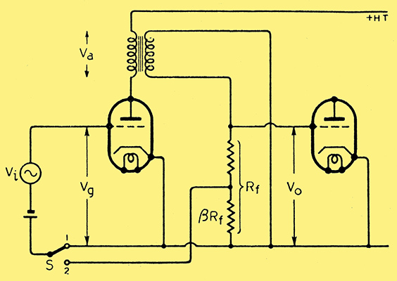
Fig. 1. Transformer-coupled voltage amplifier with provision for feedback.
Consider a stage of voltage amplification with transformer coupling (Fig. 1). The switch S is arranged to apply feedback from the secondary of the transformer when in position 2. In position 1 no feedback is applied, and providing the resistance Rf of the potential divider is adequately high, a frequency / gain characteristic as sketched in the top curve of Fig. 2 is likely to result.
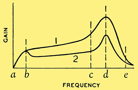
Fig. 2. Frequency/gain characteristics of circuit of Fig. 1, corresponding to switch positions (1) and (2).
It reveals a poor low-frequency response below b, a resonant peak at d then a falling off rapidly towards e.
Obviously this characteristic is associated with serious frequency distortion and the cure would seem to lie in applying negative feedback rather than redesigning the transformer. Suppose then that the switch (Fig. 1) is thrown into position 2. Assuming that the feedback potentiometer has been suitably connected (otherwise self oscillation is probable) the result will be disappointing, as is shown in the lower curve of Fig. 2. The gain is generally lower than before, but instead of a flatter characteristic it will be adorned by an additional 'bump' at b, the obnoxious one at d still being present.
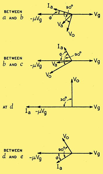
Fig. 3. Vector relations between grid voltage Vg, transformer primary voltage Va, secondary voltage Vo and anode current Ia in the amplifier of Fig. 1 without feedback and at the frequencies indicated in Fig. 2.
The simple truth is that neither below b nor at d does negative feedback obtain. This is explained by the vector diagrams of Fig. 3, they are based on the fact that the coupling transformer is in effect a complicated network of mutual inductance, leakage reactance L, shunting capacitances on primary and secondary (C), etc. This is more fully treated elsewhere [5] Communication Engineering, 2nd Edition, W L Everitt, p. 454, etc., and roughly indicated here by Fig. 4.
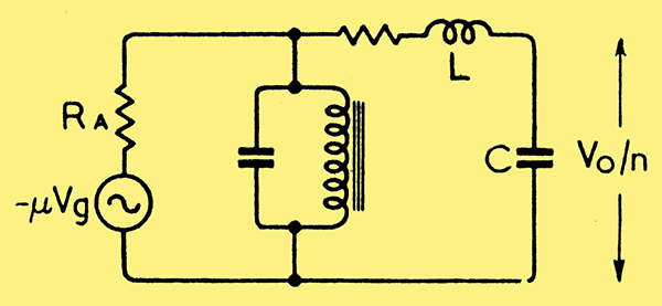
Fig. 4. Simplified equivalent circuit of valve and transformer at frequencies above (c) in Fig. 2.
Hence, while the secondary voltage Vo is always very nearly 90° out of phase with the primary current Ia, the phase angle between the anode circuit EMF - μVg and Ia varies from a slight to a large lagging angle as the frequency increases from a to and beyond b, since the effective load in this region is mainly the primary inductive reactance which increases with frequency. But at some point between b and d the transformer primary becomes effectively by-passed by the series combination consisting of L and C. The angle Φ thus decreases again, becoming zero at d where L resonates with C. Hence the output voltage is in quadrature with Vg at this frequency and feeding back a fraction of the former in the way shown would not provide negative feedback. Hence the hump at d is, if anything, increased relatively. Beyond d the load is likely to be capacitive on account of the primary shunt capacity and a small amount of negative feedback may obtain once more.
Again, at the low frequency end below b the anode load is small but inductive, hence Ia is nearly in phase with - μVg and Vo very nearly in quadrature with it; so feedback would not be negative with the connections shown. As shown by the fall of the characteristic, it does become so above b. Incidentally, this is a resonance like effect although no capacity is present; it might be put to good use in special circuit work where a low frequency 'resonance' is desired without a bulky capacitor.
The basic cure for the resonant rise in the frequency characteristic is not to use feedback, but to eliminate it by some known stratagem, such as a resistance shunt on the secondary. This would also modify the. phase-frequency characteristic suitably and allow of negative feedback at any frequency above b.
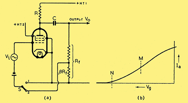
Fig. 5. (a) Circuit of resistance capacity coupled pentode amplifier with provision for negative voltage feedback. (b) Dynamic characteristic of pentode with resistance load.
Thus, it seems axiomatic that feedback can correct frequency distortion in voltage amplifiers If, and only if, the distortion is not due to series-resonance.
Now, the conventional analysis referred to is formally correct; hence the reason for possible failures in practice must be sought in the underlying physical assumptions. What tends to be over looked is the question of how the distortion term D arises in the first place, and by what mechanism, if any, negative feedback may reduce it. As a simple example, consider the circuit of a resistance-capacity coupled amplifier with pentode valve, as shown in Fig. 5 (a) switch S being in position 1. As is well known, the mutual or Vg/Ia characteristic of a pentode with load approximates less to a straight line than that of a corresponding triode circuit; in fact, as Vg gets less negative, the characteristic tends to flatten out.
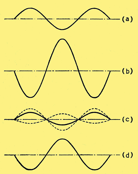
Fig. 6. Waveforms of 'instantaneous' voltages in the amplifier of Fig. 5 (a) with, for the sake of clarity, m = 3 and β = 1/3. (a) Sine wave input voltage. (b) Output voltage without negative feedback. (c) Effective input voltage (full line) made up of the original sine wave input and a fraction β 1/(1 + ImβI) of the distorted waveform (b). (d) Output voltage with negative feedback (where m = 3 for the positive half cycles falling to 2.5 for the negative). It should be noted that curves (c) and (d) are approximations only, and an 'infinite series' method would be necessary to arrive at the true waveform.
Thus, what happens when an operating point such as M in Fig. 5 (b) is chosen and a pure sine voltage Vi is applied to the input terminals of the circuit of Fig. 5 (a) is roughly as shown in Fig. 6 (b): the output voltage suffers amplitude distortion, its negative half cycles being flatter than the positive. This state of affairs is termed 'second harmonic distortion' as the output voltage is here practically equivalent to the sum of two sine voltages, one having the frequency of the input voltage, and a smaller one of twice that frequency.
Suppose now that we apply negative feedback in the circuit of Fig. 5 (a) by moving the switch S from position 1 to position 2. Assuming the blocking capacitor C to have negligible reactance compared with the resistance of the feedback potentiometer Rf, the feedback will be purely negative, i.e., the actual grid-cathode voltage (alternating component) will be the sum of the input voltage Fig. 6 (a) and a fraction β of the voltage drawn in Fig. 6 (b): this resultant is drawn in Fig. 6 (c) and differs from the original input of Fig. 6 (a) both in amplitude and form. In particular, the positive half cycles are larger than the negative. On working it out you will see that this is exactly what is required to make the output voltage less distorted. This is indicated in Fig. 6 (d), showing an improvement over Fig. 6 (b) at the cost of reduced gain.
The above explanation may be generalised in the statement that for negative feedback to reduce amplitude distortion, the distortion must be present at the input terminals of the feedback network (which in Fig. 5 (a) are identical with the amplifier output terminals) and that both the amplifying and the feedback paths must be able to pass the correcting voltage freely.
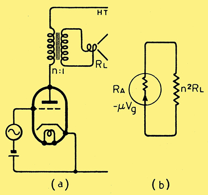
Fig. 7. Triode output stage with loudspeaker load. (b) Equivalent circuit.
As an example of distortion occurring at a point beyond the input terminals of the feedback network, consider an output stage, such as in Fig. 7 (a). It is conceivable that the loudspeaker impedance is non-linear, i.e., that it draws a distorted current in spite of sinusoidal voltages both on the primary and secondary sides of the output transformer. For simplicity, let us assume the latter to be perfect and the valve of zero internal resistance. It then requires no further argument to show that in Fig. 7 (a) the feedback (or, more precisely, its negative, component) cannot combat this type of distortion.
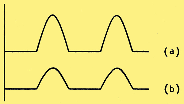
Fig. 8. Output voltages with operating point N in Fig. 5 (b) and sine-wave input. (a) Without negative feedback. (b) With negative feedback. Amplitude reduced, but waveform practically unchanged.
Let us revert to Fig. 5 (a) for an illustration of the third postulate for successful negative feedback. Suppose the grid bias be chosen too large, shifting the operating point to cut-off, say, at N of Fig. 5 (b). The output voltage will then have the rectified appearance of Fig. 8 (a) and on applying negative feedback, this is changed to Fig. 8 (b) with its smaller magnitude but practically identical waveform. This is due to the inability of the amplification path to amplify the negative half cycles of the input voltage, even though the fed-back voltage does not affect them.
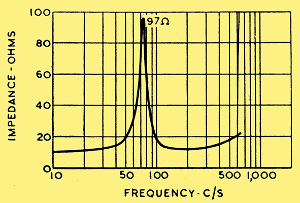
Fig. 9. Typical moving-coil loud-speaker impedance curve in the vicinity of the bass resonance.
Assuming, however, that your amplifier satisfies the conditions already postulated, there is another case worthy of careful attention. It concerns the power output stage and frequency distortion. Briefly, the loudspeaker, being a complex electro-mechanical system, is subject to some form of resonance at several frequencies; most serious perhaps is the lowest one, usually around 100 Hz. The electrical impedance of the loudspeaker is then almost purely resistive, rising to several times its normal value, i.e., from 10 to about 100Ω in the case illustrated in Fig. 9. The upshot of this is that at the resonant frequency, the output power tends to rise many times, due to an undesired improvement in the transfer efficiency of electrical into mechanical power.
Now, when a triode is used, the load is matched to the valve; hence an increase in the normal load value will decrease the power available in the load and the 'low-frequency boom' will be less serious than might be feared. In other words, a comparatively low anode resistance damps the loudspeaker resonance electrically. On the other hand, power pentodes or beam tetrodes have the advantage of greater efficiency and sensitivity over triodes; but they tend to give greater distortion, partly due to the curvature in the mutual characteristic (see Fig. 5 (b)) which produces amplitude distortion, and partly due to their high internal resistance the latter being normally so high that there can be no question of matching the speaker. At resonance, speaker power will tend to rise with the resistance, producing very serious frequency distortion.
The analysis of the above is as follows and may help in understanding the problem better; for a Class A operated valve and its equivalent circuit (Figs. 7 (a) and (b)) we may write down, neglecting loudspeaker reactance,
p> P = | (μVg)2/n2RL . (n2RL/(RA + n2RL))2 = (μVg)2/n2RL . 1/(1 + RA/n2RL)2 |
|
Where:
p> μ = | valve amplification factor. |
|
p> RA = | valve slope resistance. |
|
p> RL = | AC resistance of voice coil. |
|
p> n = | output transformer ratio. |
|
p> P = | electrical power supplied to the speaker. |
|
At the resonant frequency, the speaker resistance rises to 10 RL, say, hence the electrical power in it, P (res.), rises to:-
p> | (μVg)2/10n2RL . 1/(1 + RA/10n2RL)2 |
|
For the desired damping effect to occur, i.e. P to fall as RL rises, examination of the last equation indicates that RA must be small compared with n2RL. Indeed, if RA were zero, P (res.) would be equal to P/10, or P would vary inversely with RL, i.e., damping would be ideal. Conversely, if RA is very large compared with the effective load resistance,
and P (res.) = 10P, i.e., P would vary directly with RL and resonant 'boom' would be increased still further!
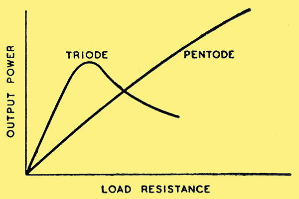
Fig. 12. Output power for given input voltage and variable load resistance; triode and pentode respectively.
This is roughly illustrated by the graphs of Fig. 12.
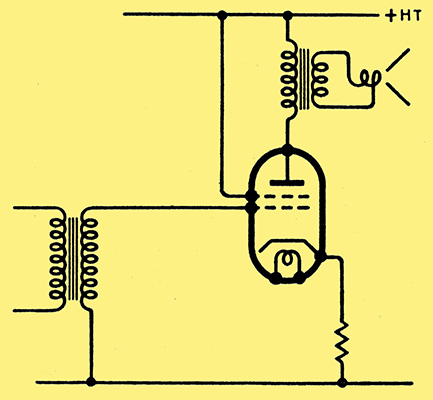
Fig. 10. Beam tetrode output stage with negative current feedback obtained by omitting the cathode by-pass capacitor.
Negative feedback is thus called for. There are two basic ways of applying it, either as current or as voltage feedback. The former is readily achieved by leaving off the by-pass condenser across the self-bias resistor in the cathode lead (Fig. 10): while this reduces amplitude distortion, it will actually increase the frequency distortion, for this step has the effect of increasing the anode resistance by the factor (1 + |mβ|).
On the other hand, voltage feedback decreases RA by the factor (1 + |mβ|) and will thus look after both forms of distortion in pentode power stages. The outline of a suitable circuit is shown in Fig. 11; it forms the basis of handling pentodes in push-pull circuits.
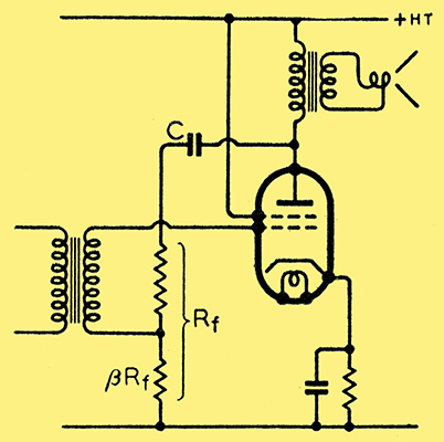
Fig. 11. Tetrode output stage with negative feedback correctly applied as voltage feedback through C and Rf.
Note that the feedback potentiometer should have a high value compared with the reflected speaker resistance n2RL.
Thus you will see that in applying negative feedback to a circuit, it is necessary not only to make sure that the feedback is truly negative, and does not affect the operating point, but also that it can achieve your requirements in principle.
References
- Regeneration Theory, H Nyquist: Bell System Technical Journal, Jan., 1932.
- Radio Engineering, 2nd edition, F E Terman, or Communication Engineering, 2nd Edition, W L Everitt, p. 463, etc.
- Reducing Variations in Amplification by Means of Negative Feedback, J Peters, Hochfrequenztechmk u. Electroakustik, p. 46, Feb., 1942 (in German).
- Feedback, E K Sandeman, Wireless Engineer, Aug., 1940.
- Communication Engineering, 2nd Edition, W L Everitt, p. 454, etc.
|