|
Negative Feedback
With negative feedback we apply a fraction of the output signal to the input of an amplifier in anti-phase. That is, the signal fed back is 180° out of phase with the input signal to the amplifier.
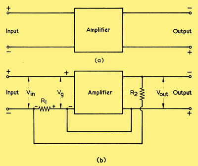
(a) A simple amplifier without negative feedback
(b) By adding R1 and R2 in the circuit shown here, negative feedback is provided between the input and output terminals.
(a) illustrates a straightforward amplifier to which no negative feedback is applied. If a signal input voltage is fed to the two input terminals in this diagram, an amplified signal voltage appears at the output terminals. Plus and minus signs have been added at the input and output terminals, these indicating the polarities of the signals during one half-cycle of the input signal.
In (b) we connect resistors R1 and R2 in series across the output terminals, the voltage across R1 now being inserted between the lower input terminal and the corresponding input point of the amplifier. Again we have plus and minus signs to indicate signal polarities and we now add three terms to indicate signal voltage amplitudes. These are Vin, to indicate the signal voltage applied to the input terminals of (b); Vg, to indicate the signal voltage applied to the amplifier proper (the subscript 'g' infers an input control grid circuit); and Vout, to indicate the signal voltage at the output. It will be seen that, due to the polarity of the fraction of the output signal which appears across R1, an out-of-phase signal voltage is inserted in series with Vin and the input of the amplifier, with the result that Vin must always be greater than Vg.In other words, to achieve the same output voltage the signal applied to the input terminals in (b) must always be greater than the signal applied to the input terminals in (a). By adding resistors R1 and R2 in the manner shown in (b), we have introduced negative feedback, with the consequence that the overall gain - from input to output terminals - has been reduced.
The loss of gain resulting from negative feedback is, of course, a disadvantage but, as we shall show, the negative feedback provides a number of important advantages which considerably outweigh this disadvantage, particularly with respect to audio frequency amplifiers. Indeed, the major practical application of negative feedback is to improve the performance of AF amplifiers, or of other low frequency amplifiers which are required to provide a low-distortion output.
A simple and interesting mathematical exercise will demonstrate one of the results of adding negative feedback to the amplifier of (a) so as to give the circuit of (b).
The voltage gain of the amplifier proper is Vout divided by Vg and we may denote this by the letter A. Thus:-
A = Vout/Vg or, Vout = AVg.
Since R1 and R2 form a fixed potentiometer, the fraction of the output voltage appearing across R1 is R1/(R1 + R2). Let us call this fraction n. The voltage appearing across R1 is thus nVout.
Vin is greater than Vg by the signal voltage across R1, so:-
Vin = Vg + nVout
Substituting for Vout from our previous equation, we get:-
Vin = Vg + nAVg
= Vg(1 + nA)
Thus, Vin has to be (1 + nA) times greater than Vg to achieve the same output; or, the negative feedback has caused Vin to be divided by (1 + nA) before application to the amplifier proper. The expression (1 + nA) is sometimes referred to as the feedback factor.
It follows that the overall gain with feedback is A divided by (1 + nA), ie:-
Overall gain = A/(1 + nA)
If the product of A and n is large we then encounter the remarkable fact that, regardless of the gain of the amplifier without feedback, the overall gain with feedback is always nearly equal to 1/n. For instance if n is 1/20 (whereupon 1/n = 20) then for A = 2,000 we have an overall gain of 19.8, for A = 1,000 we have an overall gain of 19.6 and for A = 500 we have an overall gain of 19.2.
Gain Reduction
It follows from this that one of the results of applying negative feedback to an amplifier is that the overall gain with feedback tends towards a constant figure despite the fact that the gain of the amplifier without feedback may vary considerably. The tendency towards a constant overall gain figure is most pronounced when the gain without feedback is high and a relatively large fraction of the output voltage is fed back to the input. A typical form of distortion in an AF amplifier occurs when some frequencies are given greater amplification than others. Applying negative feedback to such an amplifier causes the overall gain at all frequencies to tend towards a constant figure, with the result that the amplifier exhibits a smoother frequency response characteristic. That is to say, whereas a curve showing amplifier gain at various frequencies might exhibit pronounced peaks or troughs before feedback was applied, the overall gain curve after feedback has been added would be smoother and 'flatter'.
Harmonic Reduction In addition to improving the frequency response of an AF amplifier, negative feedback may also reduce the effects of distortion introduced by the amplifier itself.
Let us assume that the amplifier of (a) introduces a certain amount of distortion and that we apply a sine wave signal to its input terminals. We will then obtain an amplified, but distorted, sine wave at the output terminals. The distorted output will, in fact, consist of the original pure sine wave plus a number of harmonics of that sine wave.
In (b) we introduce negative feedback and apply a fraction of the output signal in series with the input signal. The sine wave fed back to the input circuit is in anti-phase with the input signal, and there is a reduction in the overall gain of the sine wave following the lines we have already described. With the harmonics introduced by the amplifier, however, the effect is somewhat different because such harmonics were not present in the original signal. What the negative feedback circuit is, in effect, doing here is to inject into the input of the amplifier a series of harmonics which are opposite in phase to the harmonics created in the amplifier itself. The result is that the harmonics resulting from distortion in the amplifier tend to be very nearly cancelled out, and the amplifier output consists of the original pure sine wave together with a lower harmonic level than was evident before negative feedback was applied. It can be shown that the harmonic level is reduced due to negative feedback by the same ratio as is the amplifier gain. Thus, if the amplifier without feedback has a gain of 1,000, and the feedback has resulted in an overall gain of 20, the harmonics introduced by distortion will be reduced 50 times. If the harmonic distortion was 5% before feedback was added, after feedback it becomes 0.1%. It is important to note that this ratio of reduction in harmonic distortion applies for the case where the same output voltage is given with feedback as was previously given without feedback.
By the same reasoning, it may be seen that other spurious signals generated in the amplifier are also reduced by the application of negative feedback. The spurious signals normally encountered are hum (due to inefficient mains supply filtering circuits and unwanted couplings between the amplifier circuits and mains power supply wiring and components) and noise. Noise is mainly generated in valves and resistors, and appears as a hiss in the output of the amplifier.
Noise due to valves and resistors is mainly troublesome if they appear in an early stage of the amplifier, whereupon there is a high level of subsequent amplification. To help in reducing noise, special low-noise valves are available, as also are high-stability resistors. The latter offer a lower noise level than do the normal composition types available in 1968. In later decades much better passive components have been developed.
Negative feedback reduces hum and noise generated in the amplifier by the same amount as it reduces harmonic distortion due to the amplifier. As with harmonic distortion, this relation holds true when the output voltage is the same after the application of feedback as it was before.
Yet a further advantage provided by negative feedback is that it helps to stabilise the performance of an amplifier. Since the gain given with feedback tends towards a constant figure regardless of the gain offered without feedback, it follows that variations in performance due to valve ageing, different component values within tolerance, and the like, will have less effect on overall performance when negative feedback is applied.
Output Power
Negative feedback confers a number of important advantages, and these are of particular value in AF amplifiers which are intended for good quality or high fidelity reproduction. The main disadvantage of negative feedback is that the overall amplification is reduced. Indeed, negative feedback offers the greatest improvements in performance when the gain without feedback is considerably higher than the gain with feedback. For best results, negative feedback has to cause a large reduction in overall gain.
In practice, this loss in gain is not a great inconvenience because it is possible to obtain a high level of gain before feedback is applied by means of voltage amplifier stages, and voltage amplifier stages are relatively inexpensive in terms of valves, components and HT supply requirements. The most expensive stage in an AF amplifier is normally the output stage, which requires a power valve (or valves), the output transformer and a high HT supply current. An output stage offering an output power approaching the maximum of which it is economically capable introduces considerably more distortion than does a voltage amplifier stage. Also, as we have seen in recent articles, the distortion introduced by an AF output stage increases with output power. If we were to avoid the use of negative feedback, one method of obtaining a low distortion output would consist of employing an output stage capable of providing considerably more output power than we actually intend to use. Such an output stage would, however, be very uneconomical in terms of valves, components and HT supply requirements. A much cheaper method of obtaining a low distortion output at the required power would consist of using an output stage working near its economic maximum and applying negative feedback from the output back to a preceding voltage amplifier. We would then obtain the same output power as without feedback but at a much reduced distortion level, and all we would lose would be the gain provided by a low-cost voltage amplifier stage.
Domestic valve radios and television receivers either have no negative feedback circuits or, at best, provide only a low level of negative feedback in their AF amplifying stages. This is because equipment of this nature is manufactured at highly competitive prices which do not permit the inclusion of voltage amplifier stages whose gain is to be largely cancelled out by negative feedback. For most people, the standard of reproduction without feedback given by equipment of this nature is considered to be acceptable. On the other hand, high quality and high fidelity reproducing equipment, which is not subject to quite the same stringent price limitations, may incorporate a number of voltage amplifying stages whose gain, due to the use of negative feedback, is partly or completely nullified.
Feedback Circuits
In diagram (b) we applied negative feedback from the output to the input of an amplifier, the latter being shown in block form. This diagram demonstrates voltage feedback because it is a signal voltage which is fed back. An alternative type of negative feedback involves the feeding back of an output current, and is known as current feedback. Current feedback is not employed in quite the same way as is voltage feedback, and we shall discuss it in more detail in a later article.
Another term which needs to be introduced at this stage is feedback loop. This term applies to the composite amplifier from the input terminals to the output terminals and then back to the input again via the feedback circuit.
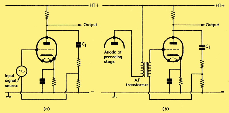
(a) Applying negative feedback over a single amplifying stage
(b) For the circuit of (a) to be practicable, the preceding valve has to be coupled to it via an AF transformer
Some voltage feedback circuits appear in the next four diagrams. Illustration (a) shows a circuit following the same basic principles as the block diagram (b) that we have been discussing. Here, a fraction of the signal voltage at the anode of the valve is fed back via capacitor C1 (assumed to have negligible reactance at AF) so that it is in series with the source of input voltage, which is depicted as an AC generator. Since the voltage at the anode is out of phase with the input signal, the circuit gives negative feedback. This circuit suffers from the practical shortcoming that neither side of the source of input signal is at chassis potential. It would be impossible to precede the circuit with a voltage amplifier stage having a common chassis connection unless an AF transformer were used for coupling, as in (b). Since an AF transformer is liable to introduce more distortion than resistance-capacitance coupling, the circuit of 2 (b) is not very attractive. Nevertheless, it has the merit of illustrating basic principles, and we shall give it a little further consideration before passing on to other feedback circuits.
The circuit of (a) is useful if one amplifying valve appears in the feedback loop, as occurs in the diagram, or if three valves in cascade appear in the loop, as in (c) below.
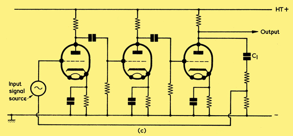
(c) Feedback from an anode to a preceding grid may also be applied over three valves
With three valves the feed back would still be negative since each valve provides 180° phase reversal of the signal. If feedback of this type was attempted with two valves, however, the feedback would be positive. Thus, feedback of the type shown in circuits (a) and (c) may only be applied over an odd number of valve amplifying stages.
In practice, there is a restriction on the number of resistance-capacitance coupled amplifying stages over which negative feedback may be applied, but we shall leave this particular aspect until later.
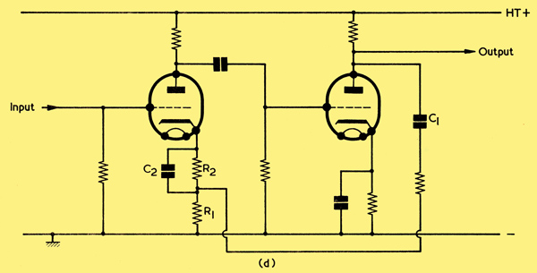
(d) When feedback is from anode to cathode, an even number of valves should appear in the loop.
In (d) there are two valves with resistance-capacitance coupling, and feedback is provided via C1 (which has negligible reactance at AF) from the anode of the second valve to the cathode of the first. R1, in this diagram, has a value lower than the normal cathode bias resistance required by the first valve, this resistance now being given by R1 plus R2. C2 is a normal cathode bypass capacitor. The fact that the feedback in (d) is negative may be ascertained by seeing what occurs when, for instance, the grid of the first valve goes positive. This causes its anode to go negative and the anode of the second valve to go positive. The cathode of the first valve then goes positive also, reducing the grid-cathode voltage change due to the initial positive-going input signal and thereby providing negative feedback. A feedback circuit of the type shown in (d), where the anode signal is,fed back to a preceding cathode, may only be employed with an even number of valves. If an odd number of valves were used, the feedback would become positive. It will be noted that the circuit of (d) allows the preceding amplifying stage to share a common chassis connection.
The next two circuits show voltage feedback circuits in which the speaker transformer appears in the feedback loop. A single valve output stage is assumed.
A great advantage conferred by having the speaker transformer in the feedback loop is that the phase of feedback may be reversed, if required, by merely transposing the connections to the speaker transformer secondary. The feedback loop can then accommodate either an even or an odd number of stages. A further advantage is that the output voltage at the transformer secondary is available at a low impedance and can be readily applied back to an earlier cathode circuit, which will exhibit a much higher impedance. Also, the negative feedback will reduce distortion due to the output transformer itself, which now enters the feedback loop.
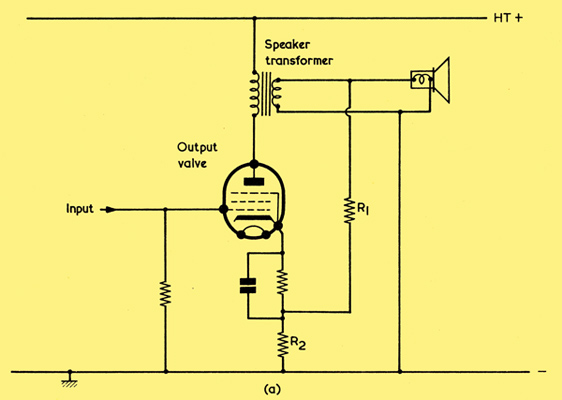
(a) A feedback loop which includes the speaker transformer. As in the previous diagram (d), the feedback is applied to a cathode circuit.
In the simple feedback circuit shown in (a) above the feedback is applied, by way of R1 and R2, over the output stage only. This circuit offers some improvement over the performance without feedback, but the full benefits which can be given by negative feedback are not realised due to the relatively low gain available in the single stage before feedback is applied.
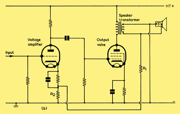
(b) Negative feedback applied to the cathode of a voltage amplifier preceding the output stage.
Above in (b) the feedback is applied over the output stage and a preceding voltage amplifier stage. This circuit is capable of offering a much better performance than that of circuit (a) because the gain without feedback is considerably higher.
Feedback from the speaker transformer secondary to the cathode circuit of an earlier voltage amplifier stage represents a very commonly used technique in valve high fidelity amplifiers. In such amplifiers the output stage will normally be push-pull, whereupon the feedback is applied to the cathode of a voltage amplifier preceding the phase-splitter. The number of stages in the loop may be catered for by connecting the speaker transformer secondary into the circuit with appropriate polarity.
|