|
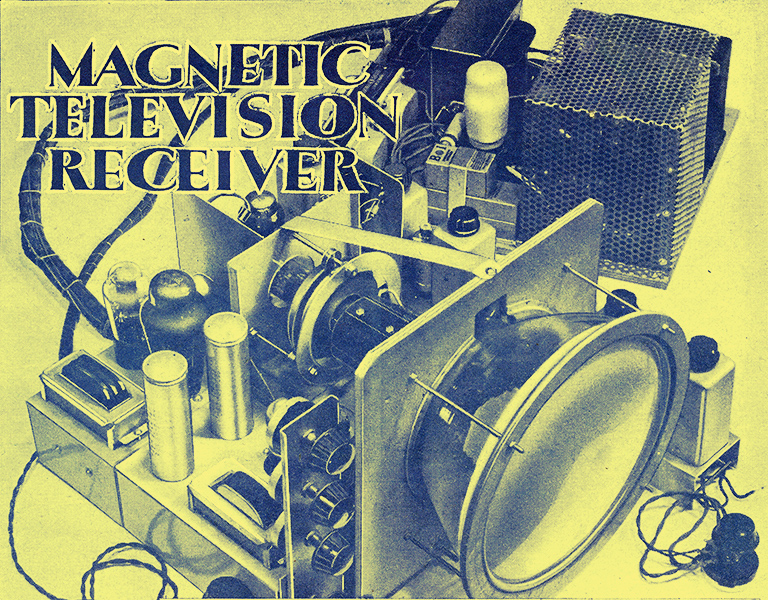
This design was the cover feature of this issue published just over a month before the advent of WWII closed the television service for the following six years.
Part 2 - RF, FC and IF receiver circuits. (Part 1 not yet in museum - ed.)
After the general preliminary discussion in Part 1 we can turn to a consideration of the actual receiving equipment. It may be of interest at this point to note that the design of this apparatus was commenced early last November. The paper design, construction of the experimental model and initial testing occupied about two months. After this another month was occupied by general testing and minor modification.
This may seem a long time, but it must be remembered that there are only two hours of day-time transmissions each day. Consequently, in a month only about forty hours testing on signals is possible. Much development work can, of course, be carried out without signals or with a local oscillator, but for many tests signals are essential.
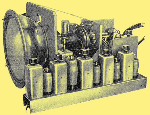
In this view of the apparatus, the receiver is clearly shown in the foreground, and above the chassis it consists simply of alternating valves and coil cans.
By the end of January the apparatus had reached practically its final form, and since then to the time of writing it has been used almost daily in The Wireless World Laboratory. During this period of four months the apparatus has never failed to give a good picture and no defects of any nature have developed. The utmost confidence is consequently felt in the reliability of the gear.
Constructionally, the apparatus is divided into two main units - receiver, tube assembly and time-base, and the power pack. The former, however, is also really in two parts; there is a main chassis of steel which carries the tube, deflecting and focusing coils and time-base, and a separate aluminium chassis for the receiver the two being bolted together to form a single unit. This is done for two reasons, first, a steel chassis is necessary for the tube assembly in order to obtain adequate rigidity and an aluminium (or copper) chassis is very desirable for the receiver in order to maintain stability; secondly, the sub-division of the apparatus makes construction easier, since the separate units are more easily wired.
The Receiver
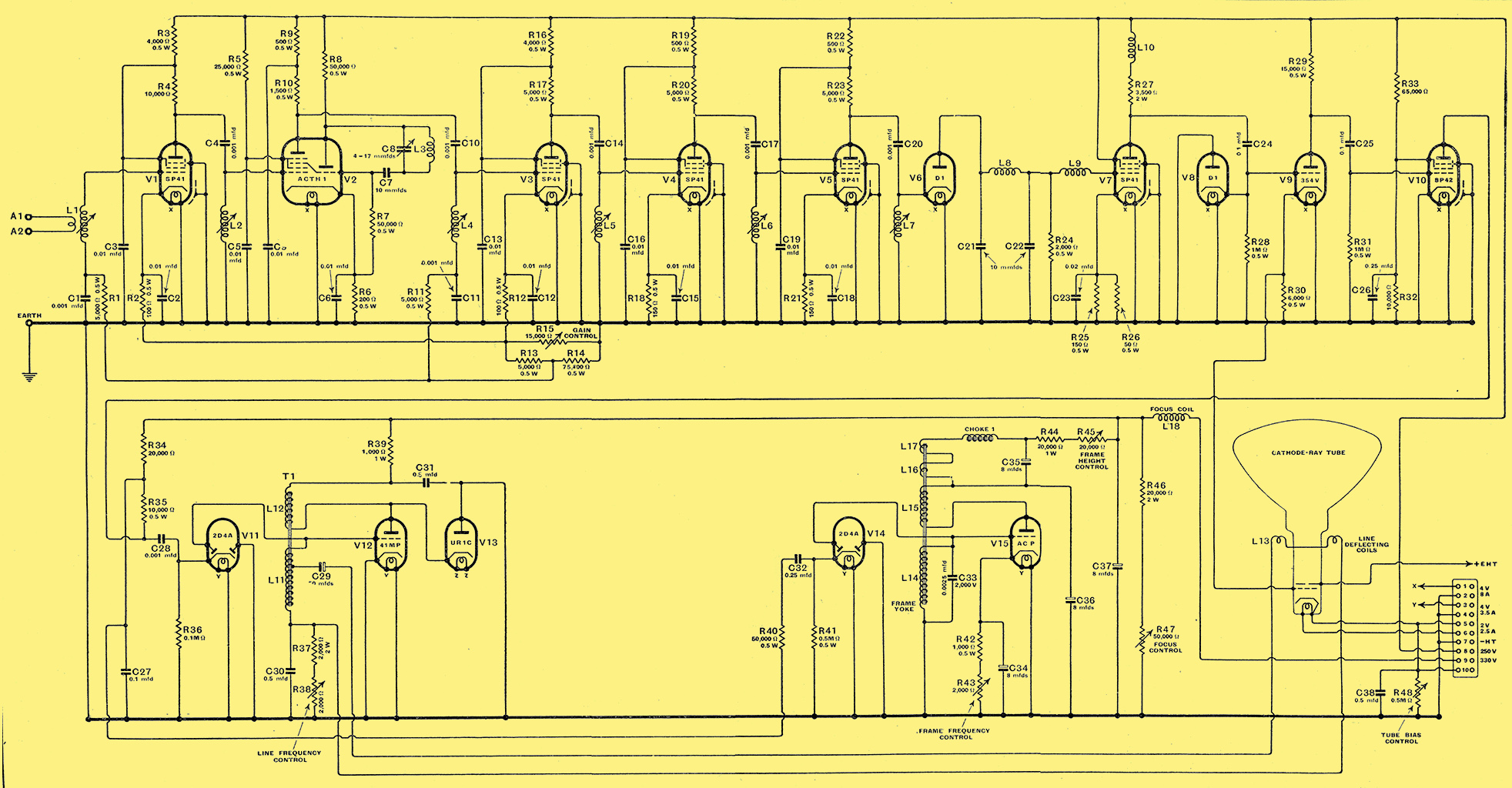
Fig. 1. Fig. 1. The receiver portion of the equipment is shown in the upper part of this diagram and the time-base in the lower. V10 is the sync separator and V12 and V15 are respectively the line and frame scanning oscillators.
The complete circuit diagram is shown in Fig. 1. The upper part of the drawing represents the receiver proper and the components are carried by the aluminium sub-chassis, while the lower part of the diagram shows the time-base and tube which are carried by the steel chassis to which the receiver chassis is bolted. Ten valves are used in the receiver and five in the time-base. Of these V1 is an RF stage and V2 a frequency-changer; V3, V4 and V5 are IF stages and V6 is a diode detector. Then comes the VF stage V7, followed by a DC restoring diode V8. There is then a combined phase-splitter and cathode-follower V9 and a sync-separator V10. In the time-base V12 and V15 are respectively the line and frame saw-tooth oscillators, and V11 and V14 are diodes through which the sync pulses are applied. V13 is another diode which is provided to damp out oscillation on the line fly-back.
An RF stage is almost essential in a sensitive superheterodyne, for as an RF valve introduces much less noise than a frequency-changer, a much cleaner background in the picture is obtained when it is used than when the frequency-changer is the first valve in the set and the IF gain is increased to maintain the same sensitivity. Although coupled pairs of tuned circuits for the inter-valve couplings enable greater gain to be obtained for a given band-width than single-circuits, the latter are adopted in both RF and IF circuits.
There are good reasons for this. The advantage in gain of two-circuit couplings is only retained if the total capacities in circuit are of the same order. With single circuits variable inductances can be used for trimming, but with two circuits this is usually very difficult to arrange and capacity trimmers must be used. This at once makes the total capacity very appreciably higher with two-circuit couplings than with single circuit. As a result their advantage is largely, if not completely, lost. They still retain the advantage of providing better selectivity, however, but this is not important if the selectivity with single circuits proves adequate, as in practice it does (There was just a single London television transmitter - ed.). The single-circuit couplings are considerably simpler to produce and adjust.
The RF Circuits
Mazda SP41 valves are used for the RF and IF stages, since they have a high mutual conductance with low capacities, and the input resistance at 45 MHz is quite high in view of the mutual conductance. It is only about 2 kΩ, which may not seem very high, but everything is relative, and it seems high compared with older valves like the AC/SP3 of similar mutual conductance.
The input circuit L1 is tuned, like all the other circuits, by the stray and valve capacities; the inductance is variable for trimming, however. The variation is obtained by a form of spade tuning, for control knob on the coil screen enables a brass plunger to be inserted to the desired degree inside the coil form. The effective inductance depends on the position of the plunger relative to the coil.
No artificial damping is introduced in this circuit because, in addition to the coil losses, the circuit is damped by the input resistance of VI, and also by the connection of the aerial feeder to the primary winding. As the valve resistance is about 2,000 Ω the total effective damping on the circuit with optimum coupling to the feeder is equivalent to a shunt resistance of rather less than 1,000 Ω. The circuit is, in fact, quite heavily damped and gives an adequate band-width in consequence.
The coupling between the RF and frequency-changer valves is by means of the tuned-grid circuit, but in view of the heavy damping which the circuit requires for the desired band-width, it is permissible to use a feed-resistance R4 instead of an RF choke. This represents a considerable saving in cost and space, since it is done in all stages.
The input resistance of the frequency-changer is considerably higher than that of the RF stage, and on this coupling there is no damping introduced by the aerial circuit. The feed-resistance R4 plays a part, but in this case it is given the fairly high value of 10 kΩ, so that it does not represent a major part of the circuit damping. The result of this is that the circuit L2 is noticeably sharper in tuning than L1.
A triode-hexode frequency-changer is used, despite the fact that an SP42 with separate oscillator will give much more gain. The 'gain' of the frequency-changer, in fact, is not far off unity. The two-valve circuit, however, is more complicated and more difficult to set up, and it seems to the writer that the extra valve can he more usefully employed elsewhere.
The so-called modified Colpitt's oscillator circuit is used and consists of L3 tuned by the capacitor C8. The coil is former-wound for rigidity and an air-dielectric capacitor is used; both are included in the same can and the capacitor has an insulated extension spindle for adjustment.
The grid capacitor C7 has a capacity of only 10 μμF, this value being selected because it gives the correct amplitude of oscillation. At first, the usual 0.0001 μF capacitor was used, but it was found quite difficult to secure the correct amplitude. It could be done, of course, by careful coil design, but there was no simple control of amplitude apart from damping the circuit by shunt resistance.
This is not a very good course because it makes the oscillator circuit poor and the frequency stability is not very good. At length it was decided to use a good coil which would normally lead to excessive amplitude, and to control the amplitude by the grid capacitor. This capacitor acts as a coupling between the valve and the tuned circuit, and so we have the desirable result of a good tuned circuit loosely coupled to the valve, both factors which make for good frequency stability.
It is not anticipated that the capacity of C7 will need to be altered from 10 pF with the valve and tuned circuit specified, but if for any reason a different valve or circuit is used the amplitude of oscillation is readily adjusted by changing this capacity. The use of the correct amplitude is rather important, because if it is too small the conversion gain falls off, and if it is too great a form of parasitic oscillation is very liable to occur.
The coupling between the frequency-changer and the first IF valve V3 is by the tuned-grid circuit, but L4 is given a value such that with the stray capacities it tunes in the region of 13 MHz instead of the 45 MHz of the signal circuits. Otherwise this coupling is the same as the RF coupling L2. All the IF couplings are alike and consist of the variable inductance with the coupling capacitor in a screening can. In this case C10 is in the can with L4 and is supplied with the coil; this is why C4, C10, C14, C17 and C20 do not appear in the list of parts. For the same reason C8 is not included; it is part of the oscillator tuned circuit assembly.
Because it is intended that L4 be tuned to the mid-band intermediate frequency and because the capacity on this circuit is higher than on the others the feed resistance R10 is given the low value of 1,500 Ω. This resistance provides the major portion of the circuit damping, for the input and output resistances of the valves are too high to have much effect at 13 MHz. The input resistance is of the order of 25 kΩ.
The two following stages V4 and V5 have identical couplings L5 and L6 with feed resistances R17 and R20 of 5 kΩ. These circuits are thus more sharply tuned, and are, in fact, rather too sharp for tuning to resonance. It is intended, however, that they be mis-tuned in opposite directions about the mid-band frequency to broaden the band-width.
The last IF circuit is L7 and couples V5 to the diode detector V6. This circuit is intended to be tuned to the mid-band frequency and is consequently damped rather more heavily than the two preceding ones. The feed-resistance R23 to V5 has a value of 5 kΩ, but the circuit is also damped by the input resistance of the detector. As this has a load resistance R24 of 2 kΩ, it would have an input resistance of 1 kΩ only under ideal conditions.
The detector efficiency, however, is only of the order of 50%, which fact alone raises the input resistance to about 2 Ω. Other minor factors enter and tend to make the resistance of the order of 2-2.5 kΩ. The external damping applied to L7 is thus equivalent to a shunt resistance of some 1.4-1.7 kΩ.
The adjustment of the circuits, and the effects obtained, will be described later in detail, for there are actually several different ways of adjusting. them to give different IF characteristics. In general, however, the intermediate frequency is 13 MHz, and for double sideband reception all IF circuits are first tuned to this frequency and then L5 and L6 are mis-tuned by roughly equal amounts in opposite directions.
This greatly broadens the response curve, and naturally the amplification falls also. The gain, however, is considerably higher than if all circuits were tuned to resonance and more heavily damped to give the same response over the pass-band. Moreover, the selectivity is higher.
The choice of 13 MHz for the intermediate frequency is dictated by practical considerations. It is found to be quite difficult to prevent harmonics of the intermediate frequency, which are necessarily generated in the detector, from being passed back to the input circuits. Very thorough filtering and screening is necessary for the complete avoidance of this feed-back, and this is often rather difficult to accomplish.
Now if one of these harmonics reaches the input circuits and falls near 45 MHz in frequency, it produces an unpleasant background to the picture. The pattern produced depends on the precise frequency relationships, but it usually takes the form of a series of light and dark parallel lines over the picture - generally diagonally across it. In more severe cases the effect is more in the nature of a very dirty background with no very noticeable structure.
The easiest and cheapest way to avoid this trouble is to choose the intermediate frequency so that none of its harmonics falls near 45 MHz. This course permits a perfectly clean background to be obtained with but little screening and filtering. There are several possible bands of frequencies within which interference is absent.
The lowest of these is a narrow band just under 7 MHz. As the intermediate frequency is increased above this the clear bands progressively become wider. There is a moderately wide band centred on 10 MHz, and one of just over 2 MHz in width centred on 13 MHz. There is also one of more than 5 MHz in width centred about 18.5 MHz.
It is an advantage to work in a wide, clear band, but it is inadvisable to make the intermediate frequency too high, since then the difficulty of maintaining stability becomes more serious. On all counts 13 MHz proves the best compromise and one which is in practice entirely satisfactory. The factors affecting the choice of intermediate frequency have been dealt with in greater detail in a previous article [★] Wireless World, March 10, 1938.
IF Filter Circuits
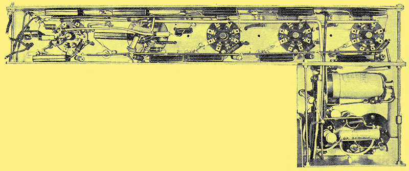
The RF, FC and IF stages are mounted on the long channel section of the receiver chassis, while the side section carries the detector, VF stage, DC restorer, phase splitter and sync separator.
The coil L8 is chosen to have an inductance which resonates with its self-capacity at about 13 MHz, so that at this frequency it offers a very high impedance and gives good filtering in conjunction with C22. Its main purpose is to prevent appreciable IF voltages being developed on the grid of V7, where they would tend to overload this valve and also reduce the IF stability through increasing the possibilities of feedback. The coil used is actually a standard superheterodyne coil, the Wearite PA6 of 37.5 μH inductance. Only one winding is used. This coil was selected because it proved entirely satisfactory, and is an inexpensive standard component.
At frequencies above 13 MHz the circuit L8 with its self-capacity behaves as a capacitor, and gives very little filtering action to the harmonics of the intermediate frequency, Those in the neighbourhood of 45 MHz - the nearest are 39 MHz and 52 MHz - are especially important, and the second filtering stage is provided to confine them to this circuit. This comprises an USW choke L9, which functions in conjunction with the input capacity of V7.
Before turning to the VF stage, it will be advisable to deal with certain other points in connection with the earlier circuits. V4 and V5 are both run close to their maximum rating to secure full gain and the greatest voltage handling capacity. The HT line is 250 Volts and both anode and screen are fed from this through 500 Ω resistances R19 and R22. Decoupling capacitors C16 and C19 of 0.01 μF capacity and of the mica-dielectric type are provided. Common decoupling is used for anode and screen circuits. Bias is obtained by means of 150 Ω cathode resistances.
In the case of the RF and first IF valves, it is desirable to be able to vary the grid bias for gain control purposes. This at once introduces difficulties. Merely to increase the bias would also increase the input resistance and change the input capacity. Both would be important in the case of the RF valve, but only the capacity change would exercise an appreciable effect on the performance in the case of an IF stage. Experience shows that the changes of tuning and damping brought about by altering the grid bias do noticeably affect the picture quality.
Fortunately, the trouble can be overcome by suitably biasing the suppressor grid as well as the control grid. For the SP41 valves, the suppressor bias must be about fifteen times the control grid bias.
This is arranged quite simply by the network shown in Fig. 1. V1 and V2 are each provided with their own initial bias resistances, R2 and R12, of 100 Ω, which also provide decoupling. These resistances are taken to chassis through a common variable resistance R15 of 15 kΩ, which acts as the gain control. The suppressor grids are taken to chassis, so that the full voltage developed across R15 is applied as negative bias to them.
The control grids are taken through decoupling resistances R1 and R11 to a tapping on a voltage divider connected across R15. This comprises R13 and R14, and the values are chosen so that one-fifteenth of the voltage across R15 is applied as negative bias to the control grids. These valves are also run at a lower anode and screen voltage than the others, the decoupling resistances R3 and R16 having a value of 4 kΩ.
This system works very well in practice and completely removes any visible effect on the picture quality of bias voltage changes. The control of two stages gives quite a wide range and, except in extreme cases, makes it unnecessary to use an attenuator in the input when receiving strong signals.
|