|
The Diode
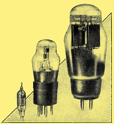
Types compared. A single diode detector for television, a duo-diode type, and right, a full-wave HT rectifier.
The simplest valve of all and the first to be produced is the diode. As its name implies, it has only two electrodes an anode and a cathode. It does not amplify, and is used mainly as a rectifier. Briefly, the cathode acts as a source of electrons which are attracted to the anode when this electrode is positive and repelled from it when it is negative.
The cathode is thus quite important, for it acts as the source of electrons; in modern valves it is one of two types - directly or indirectly heated. The directly heated cathode, and this applies to all valves, not merely to diodes, consists of a filament which is heated by the passage of current through it. At a certain temperature electrons are emitted in great quantity, and this is the normal operating condition. This normal temperature depends on the filament material and upon the emission required.
In the early days filaments were usually made of tungsten, and were operated at temperatures of the order of 2,000 - 2,5000 K. Quite a large amount of power was necessary to raise the filament to this temperature, and a typical valve would consume about 0.8 Ampere at 4.5 Volts.
Thoriated tungsten filaments followed and gave much more emission for the same operating temperature. Usually, however, they were worked at a lower temperature, and the filament of a normal valve consumed about 0.25 Ampere at 5 Volts.
Coated filaments were also used. With these the filament proper acts as a core, and there is deposited on its surface a coating which is often a mixture of barium and strontium. Such a filament can be operated at only 850 K, and needs only one-tenth the power of the tungsten type.
Directly heated cathodes of the filament type are still very widely used, being fitted to nearly all battery valves. They are also adopted for large-power triodes and for many diode rectifiers.
The indirectly heated cathode, as its name implies, is not raised to its working temperature by passing a current through it, but is heated by the conduction of heat from a nearby body at a higher temperature. In practice, the cathode consists of a tube which is coated on the outside by an emitting substance, Inside, but insulated from it, is a heater which often consists of a filament of tungsten or nickel. The passage of a current through the heater raises it to a high temperature, and it consequently brings the cathode to a suitable temperature for the emission of electrons.
The indirectly heated cathode has two advantages over the directly heated; there is no voltage drop along the cathode due to the heating current and its temperature can change only relatively slowly. The second advantage is the main reason for the use of indirectly heated cathodes, for it permits the cathode to be heated from an AC supply without hum being introduced. Only in a few cases, such as an output valve or a rectifier, is it possible to run a directly heated valve from AC without serious hum.
The chief disadvantage of the indirectly heated valve .is that the heater consumes more power than the filament of a directly heated valve. This is of little importance in mains-driven apparatus, but explains the retention of directly heated valves for battery-operated equipment. The separation of heater and cathode in the indirectly heated valve is, however, a great practical convenience, for it greatly simplifies automatic grid bias, and is often advantageous in other directions.
After this preliminary discussion of the cathode, it will be clear that this term applies to both the filament of a directly heated valve and to the heated element of an indirectly heated type. It is the electron-emitting electrode of a valve.
Let us now consider a heated cathode, naturally in vacuo, and suppose that there are no other electrodes. The cathode emits electrons which leave its surface with a certain initial velocity; their number depends on the cathode temperature and the material of which it is made. After travelling a short distance the electrons lose their velocity and fall back into the cathode. This electrode can thus be regarded as surrounded by a cloud of electrons.
The Anode-Cathode Space
Now, electrons have a negative charge, and tend to repel each other. The cloud of electrons surrounding the cathode thus tends to prevent further electrons being emitted by the cathode, and a state of equilibrium is reached at which the number of emitted electrons is equal to the number falling back on to the cathode.
This cloud of electrons is often referred to as the cathode space-charge.
Let us now consider a diode. The cathode is surrounded by an anode, which often consists of a metal cylinder. Suppose the anode is joined externally to the cathode, what happens? A few of the electrons emitted from the cathode will have sufficient velocity to reach the anode, and they will not fall back to the cathode but return through the external path and form a current.
If we now connect a battery between anode and cathode to make the anode potential negative with respect to cathode and gradually increase the voltage, we shall find that the number of electrons reaching the anode gets fewer and fewer, and eventually none do so. The negative anode repels the electrons, and only those of very high velocity can reach it; when the anode is sufficiently negative all electrons are turned back and the current ceases. The anode also exercises an electrostatic force on the space-charge and tends to move it nearer the cathode.
Now, if we reverse the polarity of the battery to make the anode positive with respect to the cathode, the anode will no longer repel electrons but will attract them. These electrons will at first be supplied by the cathode space-charge, for, instead of electrons falling back into the cathode, many of them will travel to the anode. If the potential is high enough all will go to the anode, and the normal space-charge will largely disappear, electrons emitted by the cathode passing straight to the anode.
Saturation
When this happens a further increase in anode voltage will not increase the anode current. All electrons emitted by the cathode are reaching the anode, and an increase in its voltage can attract no more. This is the saturation condition, and the anode current can be increased only by increasing the cathode temperature so that it emits more electrons. In practice, the saturation is not complete, or, rather, an increase of anode voltage above the saturation point does cause an increase in anode-current, although only a small one. This is because of a secondary effect. The anode gets hot through the work done by the electrons hitting it; the velocity of the electrons, and hence the work done, increase with the anode voltage, and the anode temperature rises. By radiation the increase in anode temperature raises the cathode temperature and hence the emission.
With most modern diodes the saturation condition cannot be reached because the cathode emission is so great that the cathode surface would be destroyed before saturation began.
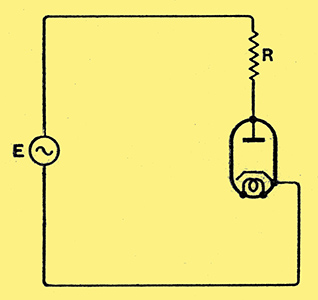
Fig. 1. - The basic circuit of a diode rectifier is shown here.
The primary purpose of a diode is rectification. The valve is connected in series with a source of alternating voltage E and a load circuit R, as shown in Fig. 1.
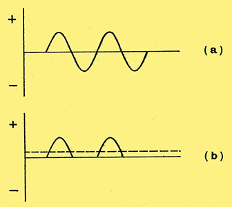
Fig. 2. - The waveform of the input voltage to the diode is shown at (a) and the rectified current at (b).
The applied voltage has a waveform such as that shown in Fig. 2 (a) and it swings the diode anode alternately positive and negative with respect to the cathode.
When the anode is positive the electrons are attracted to the anode and the current flows, but when the anode is negative electrons do not reach the anode and there is consequently no current. The current flow in the circuit is, therefore, as depicted in Fig. 2 (b); it flows in pulses on every positive half-cycle of the input voltage.
The current is pulsating and unidirectional, and it has a mean value, illustrated by the dotted line, which will operate a direct current ammeter. The pulsating current can be regarded as a direct current with a superimposed alternating current of complex waveform. By means of smoothing circuits the latter can be removed and an output of nearly pure direct current can be secured.
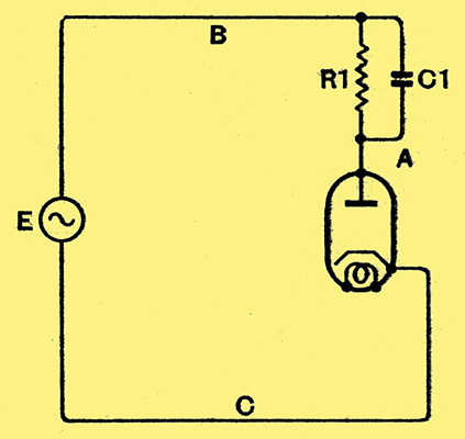
Fig. 3. - In practice, the load circuit R1 usually has a capacitor C1 across it. The operation of the rectifier is then profoundly modified.
In practice, the action of the rectifier is rather more complicated than this because the load resistance R1 is shunted by a capacitor C1, as in Fig. 3. The diode then conducts for a much shorter period than the whole of every positive half-cycle.
Consider what happens when the alternating voltage E is applied with the capacitor C1 uncharged. As soon as the anode becomes positive with respect to the cathode the valve is conducting and the electrons reaching the anode flow out into the external circuit. Very few flow through R1, for the majority flow into the capacitor to charge it. The accumulation of electrons on the lower plate (in the diagram) of the capacitor means that this plate is acquiring a negative potential with respect to the other plate.
Rectification
The voltage acting on the diode anode is thus reduced, for at the moment taken the point B is positive with respect to C by the input voltage and the point A is negative with respect to B. Consequently A is less positive than B with respect to C.
Current flows through the diode into C1 and increases the potential across it as long as the positive input voltage is greater than the voltage across C1. When the peak of the positive half-cycle of input voltage is passed the voltage falls, and as soon as it equals the voltage on the capacitor, there is no voltage applied between the diode anode and cathode and the anode current ceases.
The capacitor then commences to discharge through R1 and the voltage across it falls. The discharge is not completed by the time the next positive half-cycle of input comes along, and the diode again passes current when the positive input voltage exceeds the negative voltage on the capacitor. After a few cycles a steady state is reached when the electrons leaving the capacitor through R1 during the non-conductive time of the diode are equal to those entering it through the valve when the diode is conductive.
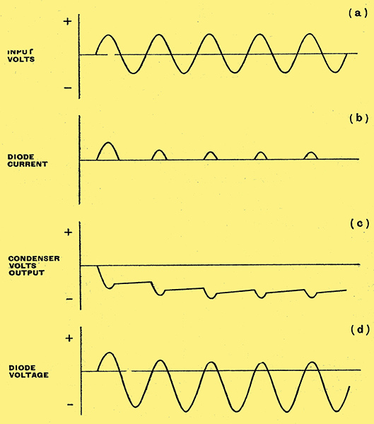
Fig. 4.- When a reservoir capacitor is used the action is as depicted in these diagrams, where (a) represents the input voltage waveform. The current through the diode is depicted at (b) and the voltage across the capacitor at (c). The voltage between anode and cathode of the diode is shown at (d).
This state of affairs is sketched in Fig. 4, where (a) shows the input voltage E and (b) depicts the diode current, The capacitor voltage is sketched at (c) and the voltage between the diode anode and cathode at (a). It will thus be clear that the ordinary rectifier conducts current for only a small portion of the cycle of input voltage, and that this time decreases as the values of C1 and R1 increase. This is clear when it is remembered that the loss of voltage across C1 during the non-conductive period of the valve increases as the product C1 R1 is reduced. it In the limit, with C1 R1 equal to infinity, the voltage across C1 would not fall, and this capacitor would charge up until the voltage across it equalled the peak input voltage. The capacitor voltage would then always offset the input voltage, and the diode anode would never become positive with respect to its cathode, and so would not conduct.
This condition is never reached, of course, for we must have a current through R1, as it is to obtain this current that we use the rectifier. Nevertheless, for a given value of R1, the larger we make C1 the more nearly will the mean voltage across it equal the peak input voltage, and the shorter will be the conductive time of the valve.
To come to practical values, a valve might be rated for 250 Volts RMS input with a mean output current of 75 mA. The peak input is 250 *times; 1.414 = 354 Volts, and on no load, that is, with R1 removed, the output voltage across C1 will rise to this value. With the full output current of 75 mA. flowing through R1 the capacitor voltage will fall to perhaps 265 Volts when C1 is some 8 μF. Reducing the current to half this value by doubling R1 will cause the voltage to rise to perhaps 300 Volts. If the capacitor capacity is doubled, the voltage will also rise.
The Peak Current
It should be noted that when a capacitor is used, the maximum voltage across the valve on the negative half cycles is equal to the peak input plus the capacitor voltage. This is called the peak inverse voltage, and can reach on open circuit 2.828 times the RMS input voltage. With high-voltage rectifiers, the maximum voltage input is usually specified in terms of the peak inverse. It should also be noted that with most of the usual circuits the peak inverse voltage appears between two windings on the input transformer.
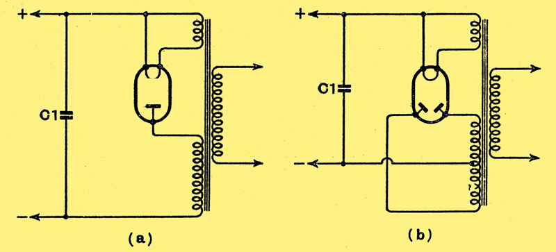
Fig. 5. - A typical half-wave rectifier suitable for a small HT supply unit takes the form shown at (a), while a full-wave rectifier is illustrated at (b).
A practical half-wave rectifier circuit is shown in Fig. 5 (a) using a directly heated type of diode rectifier. Such circuits are usually only used when low output current is required, as in small HT supply units and for high-voltage low-current supplies in television equipment. The resistance R1 has disappeared, being, of course, replaced by the apparatus which is using the output of the rectifier. Smoothing equipment is interposed between the output shown and the load circuit to remove the ripple.
In order to avoid the considerable discharge of C1 during the non-conductive time of the diode, it is common to use full-wave rectification. Two diodes are used to conduct on the opposite half-cycles of the input, and their outputs are taken in the same sense to the capacitor C1, so that it is now charged twice as often. The arrangement is shown in Fig. 5 (b). The two diodes are usually separate electrode assemblies with separate filaments, but mounted in the same glass bulb.
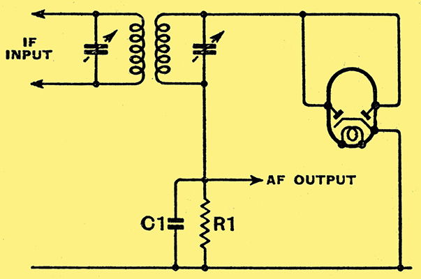
Fig. 6.- The half-wave rectifier is commonly used as a detector and the circuit often takes the form shown here.
Diodes of much smaller type but functioning in essentially the same way are often used as detectors. The most widely used circuit is fundamentally the same as that of Fig. 5 (a), and is shown in Fig. 6, where the similarity is readily apparent. The values of components are, of course, widely, different. Instead of C1 being 4-8 μF. it is 0.0001 - 0.0005 μF, and R1 is of the order of 0.25 MΩ. The input is derived from an IF transformer.
In general, detector diodes are available as a pair in one glass envelope with a common cathode. Such a valve is shown in Fig. 6, and the two anodes are strapped together so that the two are used in parallel to form one diode of greater current handling capacity. In some applications they are used separately, and some of the latest duo-diodes have separate cathodes for the two sections, giving greater flexibility of use.
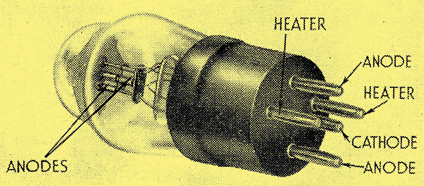
The D41. A typical duo-diode for use as a detector. Two diodes with a common indirectly heated cathode are fitted.
When used as a detector the rectified current rarely exceeds 1 mA, and is usually much less. Quite small cathode emission is needed, therefore, and the heater need consume only a small power. The whole electrode assembly can be quite small, and diodes are consequently often built into the same glass bulb as the electrode assemblies of other types of valve. The lower heater power also makes the diode one of the few valves which is available with an indirectly heated cathode in the types intended for operation from a 2 Volt accumulator.
Diodes are not only used for detection and rectification, they are also widely employed to simulate the action of a single-pole make-and-break switch! By changing the anode-cathode potential the valve can be arranged to short-circuit or open-circuit some connection as required. Used in this way a diode can give a delay on AVC action, can effect sync. separation in television, and can reduce certain types of ignition interference.
|