|
The Triode
Following upon the discussion of the diode, a further electrode is now added so that the valve becomes a triode. In this article the internal operation is explained and some of the drawbacks which led to the development of more complex types are discussed.
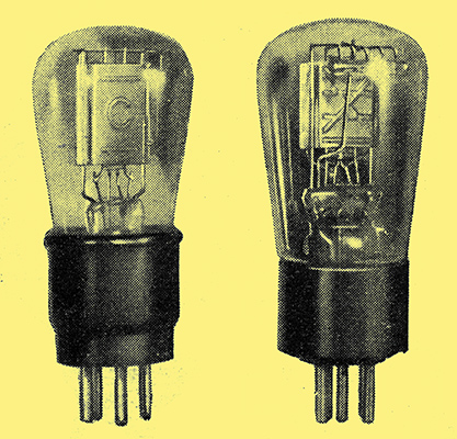
A battery triode is shown on the left and an in-directly-heated type to the right.
When discussing the diode it was shown that it gives no amplification and is in practice used chiefly as a rectifier. By introducing another electrode, so that it becomes a triode, amplification can be obtained. At one time nothing but triode amplifiers were used, but now this type of valve has been superseded for many applications by more complex structures. Nevertheless, the triode is still highly important and is the simplest amplifier.
We saw that the diode consists essentially of an electron emitting cathode, which may be directly or indirectly heated, surrounded by a metallic anode. The electrode structure of the triode is essentially the same, but between anode and cathode there is included a metal grid. This may consist merely of an open spiral of wire, or it may be a close mesh structure, depending on the type of valve. Before electrons emitted from the cathode can reach the anode, therefore, they have to pass through the spaces between the grid wires.
The action of anode and cathode is pretty much the same as in a diode, but the anode current is no longer dependent only on the anode voltage but also on the grid voltage. Under normal conditions the anode is maintained at a positive potential with respect to the cathode by the battery or other supply Ea; the potential may be some 50-300 Volts with ordinary receiving valves.
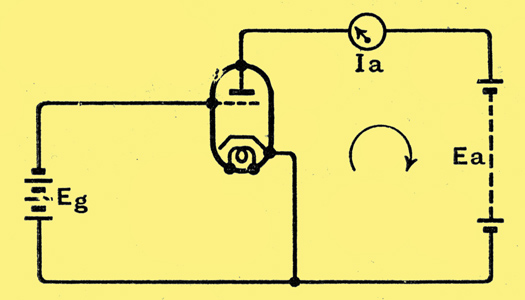
Fig. 7. - A triode valve is usually operated with a positive anode voltage Ea and a negative grid voltage Eg.
As shown in Fig. 7, the grid is normally maintained negative with respect to cathode by the battery Eg. The anode current measured by the meter depends on the anode and grid voltages and upon the electrode spacing and dimensions, and the mesh of the grid. With a given valve it depends on grid and anode voltages.
Just as with a diode, the cathode is surrounded by a cloud of electrons forming the space charge. The grid is negative and repels the electrons so that they do not pass to it. The anode is positive and acting through the interstices of the grid attracts the electrons. The electrostatic field acting on the electrons of the space charge is made up of the combined fields of grid and anode.
The grid, being the nearer to the cathode, exercises the greater influence, and a small voltage on the grid has as much effect as a large one on the anode. In practice a negative potential of 10 Volts on the grid might just counterbalance 200 Volts positive on the anode, so that the two electrodes together exercise little influence on the space charge.
If the grid is made a little less negative, the anode exercises some attractive force on the electrons of the space charge and they consequently move towards it. They do not fall on the grid because it is negative and repels them, but they pass through the gaps in its mesh. Once outside the grid they move much more readily to the anode, for not only is its full attraction exercised upon them but they are repelled by the negative grid behind them. Urged on by the pull of the anode and the push of the grid they fly rapidly to the former.
As the grid is made less negative the power of the anode on the space charge increases and more and more electrons pass through the grid to the anode. As long as the grid is negative with respect to the cathode (actually more negative than -1 Volt with indirectly heated valves) electrons do not land on the grid wires and there is no grid current.
If the grid is allowed to become positive, however, the conditions change. Both grid and anode now attract electrons and they flow from the space charge in greater numbers. Some of them now land on the grid, for they are attracted to it, and flow back to cathode through the external grid circuit and so form a grid current.
As the grid becomes more positive both grid and anode currents increase, but the anode current increases less rapidly than the grid current. Electrons which have shot through the grid no longer have the same inducement to go on to the anode. This electrode still offers the same attraction to them, but it no longer has the help of a negative grid to push these electrons towards it. Instead, there is a positive grid trying to pull them back.
Because of this some of the electrons which pass through the grid are actually pulled back to it and go to increase the grid current instead of the anode current. At length, when the grid is sufficiently positive, the anode current ceases to rise and becomes nearly independent of the grid voltage.
Grid Volts - Anode Current
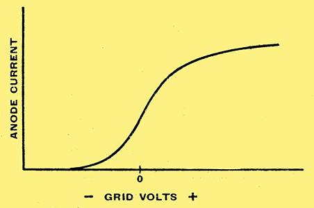
Fig. 8. - A typical triode characteristic carried well into the positive grid region is shown here.
If we plot anode current against grid voltage we obtain a curve of the form shown in Fig. 8. The curve will be different for every value of anode voltage, and we can plot a whole family of such curves for a series of different anode voltages. The shape of the curve does not change much, however, and approximately the effect of increasing or reducing the anode voltage is to move the curve of Fig. 8 as a whole to the left or right respectively.
In most cases the grid is not allowed to become positive in use and the published valve curves do not as a rule extend beyond zero grid bias; Even when positive drive is adopted the grid is not usually allowed to go so positive that the upper bend in the curve is reached. Published curves, therefore, hardly ever show this upper bend, and this accounts for the unfamiliar aspect of Fig, 8. Incidentally, at high positive grid voltages secondary emission and grid emission play a part in determining the shape of the curve, but we shall consider these in more detail when dealing with more complex valves.
When the grid is negative there is no grid current and under ordinary circumstances the valve takes no current from the voltage source applied to the grid. The valve is consequently said to. have an infinite input resistance. Actually, of course, the resistance is not infinite, for there are always a few odd electrons which manage to reach the grid and there are various leakages through defects in the insulating material. Nevertheless, the resistance is so high in comparison with the impedance of the circuits that in most cases it can be ignored.
Triode Constants
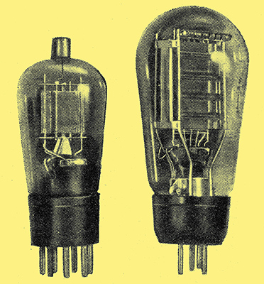
An indirectly heated amplifier triode on the left with a directly heated output triode on the right.
A triode has three 'constants' which specify its behaviour in a circuit; these are amplification factor, anode AC resistance, and mutual conductance. The standard symbol for amplification factor is μ and it is defined as the ratio of the change of anode voltage to the change of grid voltage needed for constant anode current. That is, if a valve is set up with certain grid and anode voltages it will pass a certain anode current. If now the anode voltage is changed, the anode current changes also. It can, however, be brought back. again to its previous value by altering the grid voltage, and the ratio of the voltage changes is the amplification factor. Thus, if we find that an increase of 20 Volts in the anode potential makes it necessary to make the grid potential more negative by 1 Volt to keep the anode current the same, then, μ = 20/1 = 20.
The symbol for anode AC resistance is Ra, and it is defined as the ratio of a change of anode voltage to the resulting change of anode current, the grid voltage remaining constant and current being measured in Amperes. Thus, if the anode voltage is altered by 20 Volts and the resulting change is 2 mA., then Ra is 20/0.002 = 10,000 Ω.
The symbol for anode AC resistance is Ra, and it is defined as the ratio of a change of anode voltage to the resulting change of anode current, the grid voltage remaining constant and current being measured in Amperes. Thus, if the anode voltage is altered by 20 Volts and the resulting change is 2 mA., then Ra is 20/0.002 = 10,000 Ω.
In formulae, gm is always expressed in the fundamental unit amperes per volt (A/V), but in valve tables milliamperes per volt is the more usual unit. It is only occasionally in this country that micro-amperes per Volt is used. Sometimes mho is used for A/V, and micromho for μA/V.
It should be clearly understood that these so-called constants are not actually constant, and the figures obtained depend on the operating conditions of a valve. The precise definitions of the terms thus include the statements that the changes of voltage and current must be infinitesimally small. In practice, measurements are made with grid voltage changes of the order of 0.1 Volt or less, and anode voltage or current changes of equivalent magnitude. For triodes, too, it is standard practice to take measurements with 100 Volts applied to the anode and with zero grid bias. Under normal operating conditions. somewhat different figures are usually obtained.
Now, in most applications of a triode the change of anode current which results from changing the grid potential is of no direct use. We want the valve either to produce a larger voltage change than that on the grid (voltage amplification) or to develop power in a load. To obtain this result it is necessary to connect an impedance in the anode circuit. Actually, there is no basic difference in the circuit whether a voltage or a power output is required. There is always power developed. When power is wanted, conditions are chosen so that it is a maximum, but when voltage is wanted circuit values are picked accordingly, and the power may be quite small.
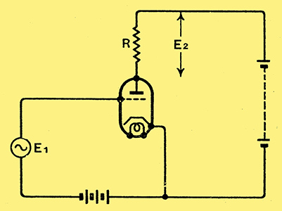
Fig. 9. - When the valve is used as an amplifier an impedance is connected in the anode circuit. In this diagram it takes the form of a resistance R.
The simplest form of coupling is shown in Fig. 9, and it will be seen that a resistance R is included in the anode circuit. The steady anode current flows through this resistance and the anode voltage of the valve - that is, the voltage between anode and cathode is less than that of the HT supply by the drop in the resistance. Thus, it the HT supply is 200 Volts and the valve passes 2 mA anode current, the anode potential is 100 Volts when R is 50,000 Ω.
Now, suppose the grid potential swings more negative, the anode current falls just as it would do if R were not there, but it does not fall as much. The drop in anode current means that the voltage drop across R is less, with the result that the anode voltage is greater. The anode consequently attracts more electrons for the given grid potential than it would do if its potential remained fixed.
Amplification
When there is a load resistance and there is a change of grid potential, there is always a change of anode current and voltage. The ratio of the change of anode voltage to the change of grid voltage is the amplification, and the product of the changes of voltage and current is the power in the load. The higher the value of the load resistance R the greater is the voltage amplification, other things being equal, but there is always an optimum value for power. This optimum value occurs when the load resistance equals the internal resistance of the valve.
In practice this condition is not often used, because we are not as much interested in obtaining maximum power output as maximum undistorted power. This is usually obtained when the load resistance is about twice the valve resistance. The precise relation depends upon the amount of curvature of the valve characteristics and upon the degree of distortion considered permissible.
We are more concerned here with what goes on inside the valve than in the precise mode of operation, including the whole of the external circuit. The latter has been dealt with many times in the past in connection with different types of circuit, and it is sufficient here to show that the change of anode current consequent upon a change of grid voltage causes a change of anode voltage.
Now, in the valve and its base and internal connections there are inevitably small capacities between the various electrodes. There is one between grid and cathode, another between anode and cathode, and a third between grid and anode. The first two are not often of great importance because they are quite small 3-15 pF - and only come in shunt with the input and output circuits. Under normal conditions only the grid-to-anode capacity is really of the first importance, and it is important because it allows a portion of the alternating anode voltage to be fed back to the grid, where it reinforces or reduces the grid voltage according to the phase.
In AF amplifiers the main effect is to make the valve behave as if it had a much higher input capacity than the true valve. Instead of being Cgc, the effective input capacity becomes Cgc + Cga (1 + A), where Cgc and Cga are respectively the grid-cathode and grid-anode capacities and A is the amplification of the valve. The effective input capacity may become 100-200 pF or more, and exercises a shunting effect on the grid circuit of the valve.
At radio-frequency, tuned inter-valve couplings are adopted, and the grid-anode capacity then results in feed-back, which normally causes instability. With both grid and anode circuits tuned there is some frequency at which the voltage fed back from anode to grid is greater in amplitude and of the same phase as the original grid voltage. It is easy to see that if the voltage fed back is equal to or greater than the original grid voltage, and is in the same phase, then the original grid voltage can be removed, and the valve will still have an adequate grid voltage, derived from the anode voltage, to maintain the anode current. It will be, of course, understood that these voltages and currents are alternating, and are not the steady grid and anode supplies.
In some cases such conditions are required, and the grid and anode circuits are deliberately coupled together, usually by means of coils. The stage is then an oscillator, and finds wide application in transmission, the superheterodyne receiver, and test apparatus. As an amplifier, however, the feed-back through the grid-anode capacity is unwanted, and in the early days many circuits were devised for avoiding its bad effects. As an RF amplifier the valve was usually employed in a neutralised. circuit, the idea being to counteract the feedback by a voltage of equal and opposite phase fed back from another point on the circuit.
Many of these neutralised circuits were extremely successful, but have fallen out of use in receivers to-day because-valves are now available with which the grid-anode capacity is exceedingly small. Needless to say, they are not triodes, and will be discussed later. Neutralising is still widely used in transmitters, however.
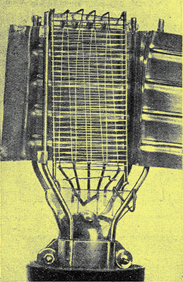
One side of the anode of an output triode cut away to expose the grid and filament assembly. The valve is directly heated and the filament can clearly be seen.
|