|
The Pentode
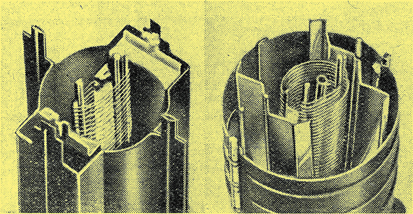
These views of the electrode assemblies of modern tetrodes clearly show the beam-forming plates. They are of the same valves as those illustrated below.
The action of the pentode is discussed in some detail in this article and its advantages over the early tetrodes are explained. Following upon this the latest tetrodes, which are in some cases replacing pentodes, are dealt with.
In the last article we saw that the main defect of the early tetrode was the presence of the negative resistance kink in its characteristic and that this kink was caused by secondary emission. In order to overcome the defect, which was of sufficient magnitude to prevent the, tetrode from forming a useful output valve, an additional grid was introduced, thus making the valve into a pentode. This extra grid was introduced solely to suppress the effects of secondary emission and it was, and still is, called the suppressor grid.
The grid is placed between the screen-grid and the anode and is usually connected to cathode. Sometimes, especially with output valves, the grid is connected internally to cathode, but it is now often brought out to a separate base-pin so that it can be connected differently when required.
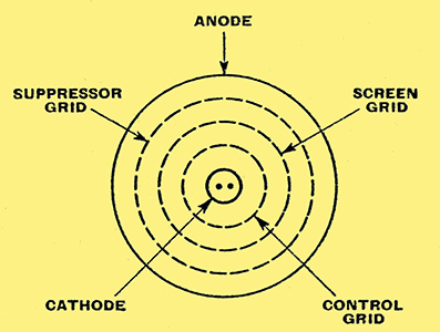
Fig. 12. - This diagram shows the general arrangement of the electrodes of a pentode.
The general arrangement of the electrodes of a pentode is illustrated diagrammatically in Fig. 12 by a series of concentric rings. It will, of course, be understood that the actual structure does not necessarily consist of such cylindrical electrodes. Other shapes are often adopted, especially for directly heated valves where the cathode is as filament running in zig-zag fashion. The electrodes are then usually in the form of rectangular open-ended boxes.
In general, the control grid is wound with a moderate mesh and the screen-grid with a close mesh. The suppressor grid, however, has a very open mesh. Up to the screen-grid the action is the same as that of a tetrode. Outside the screen, some of the electrons hit the suppressor and return straight to cathode, but the majority continue to the anode just as in a tetrode.
Some of these primary electrons arrive at the anode with sufficient velocity to knock out lower velocity secondary electrons. This again is the same as in the tetrode. Here the resemblance ceases, however, for they no longer pass to the screen in any appreciable number.
Between screen and anode there is now the suppressor-grid at cathode potential and the distance between suppressor and anode is less than that between screen and anode. Consequently, the attractive force of the screen on the secondary electrons is largely overcome. The majority of the secondary electrons thus fall back into the anode and only a few can get to suppressor or screen.
Modern Tetrodes
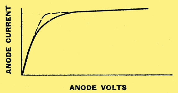
Fig. 13. - The solid-line curve shows a typical pentode characteristic and the dotted line the difference to be expected with one of the latest tetrodes.
The characteristic curve of a pentode is consequently of the form shown in Fig. 13 and exhibits no trace of any negative resistance kink. The anode voltage can be allowed to swing well below the screen voltage without trouble, with the result that the screen and anode can be operated at the same steady potential, instead of having to use an anode voltage of about double the screen voltage. This results in a large increase in power output for the same power consumption from the HT supply, so that the efficiency is increased.
As applied to RF pentodes, this form of construction results in a considerable increase in the AC resistance for a similar or higher value of mutual conductance. This means both increased amplification and higher selectivity, and when coupled with the larger voltage handling capacity makes the pentode considerably better than the early tetrodes.
Quite recently there has been a swing back to tetrodes, because it has been found possible to avoid the negative resistance kink without introducing the suppressor-grid. These new tetrodes should not be confused with the older type, for their characteristics are similar to, or better than, those of pentodes.
The obvious method of preventing the negative resistance kink in a tetrode is to tackle it at is source and stop the secondary emission from the anode. This is easier said than done, however, and it seems impracticable to effect a cure in this way, although secondary emission is naturally kept at a minimum by the suitable choice of the anode material.
One method of avoiding the negative resistance kink is to increase the anode-screen electrode spacing. As the spacing is increased the anode naturally exercises less attractive force on the primary electrons passing the screen. It consequently collects fewer of them and the anode AC resistance increases.
At the same time, the screen exercises less attractive force on the secondary electrons knocked out of the anode, so that fewer secondaries pass to the screen. At a certain critical distance between anode and screen, the negative resistance effects disappear, because the electrode spacing is such that at no anode potential can the screen gain control of the secondaries.
The characteristic curve of such a tetrode is very similar to that of a pentode, but is often somewhat. straighter and with a more abrupt bend, as shown dotted in Fig. 13. This is an advantage since it reduces distortion and increases power output. It should be noted that with both tetrodes and pentodes, the negative resistance kink may appear again in some degree at a low anode voltage when the control grid is also very negative. The combination of a low anode voltage and a highly, negative grid potential does not occur in normal operation, so this effect is unimportant in practice.
In some of the latest types of valve a rather more complex assembly is adopted. The valve is still a tetrode, but in addition to it four electrodes contain metal plates arranged to restrict the path of the electrons. These plates are not counted as electrodes because they are outside the path of the electrons.
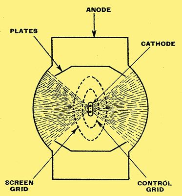
Fig. 14. - The electrode system of one modern tetrode is shown here.
The arrangement is shown in Fig.14, and it is clear that as far as the screen the action is the same as in a triode. Outside the screen, however, the electrons are not free to follow any path to the anode, but are constrained by the plates to form beams with well-defined limits.
Beam-forming Plates
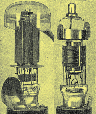
A typical modern RF tetrode is shown on the right, with an output tetrode on the left.
The electrostatic force of the anode on the electrons passing through the screen is exercised only through the gaps between the plates and consequently tends to make the electrons travel in beam formation. This tendency is accentuated by the effect of the plates themselves on the electrons. They are kept at cathode potential and as a result tend rather to repel electrons than to attract them.
One advantage of the beam formation of the electron stream is that the number of electrons per unit area is increased and hence the repelling force upon other electrons. The result is that the main electron stream itself repels secondary electrons emitted by the anode and prevents their passing to the screen.
Secondary electrons emitted at an angle, and which would normally take a long curved path to the screen, are prevented from doing so by the beam-forming plates. In other words, secondary electrons can only reach the screen through the gaps between the plates, and they are prevented from doing this by the repelling force of the primary electron stream itself. The spacing of screen and anode and the shape and position of the plates naturally play a large part in the operation of the valve.
In addition to designs of this nature, the use of control and screen grids of the same pitch is becoming more usual. In the tetrode and pentode the screen current is really waste, and if it could be reduced to zero the efficiency of the valve would be higher. By efficiency is meant the ratio of output power to the power supplied by the HT system.
Now the electrons have to pass through the control grid and this splits up the stream into a series of flat beams. It the screen is wound with the same number of turns as the control grid and is placed so that its turns are in the same planes as those of the latter, the flat beams of electrons will tend to pass between the turns of the screen without hitting its wires. As a result, a great saving of the screen current is effected.
This course is now often adopted for large output tetrodes where the saving in screen power is important. As it makes manufacture more difficult it is not adopted for smaller valves. It is also not used in RF tetrodes or pentodes because the screen must usually have many more turns than the control grid, or be of a fine mesh structure, if it is to screen grid and anode effectively.
Tetrodes and pentodes of the RF type are made in two classes, the straight and variable-mu types. The distinction is not inherent to tetrodes and pentodes, for variable-mu valves can be made with any number of electrodes from the triode upwards.
The main difference between a straight and a variable-mu valve is that the former has its control grid evenly wound; whereas the pitch of the grid turns in the latter changes along the length of the grid. As the control exercised by the grid depends upon the pitch of the winding, the amount of control exerted in the variable-mu valve varies along the length of the grid.
This means is adopted to obtain a valve with a long grid base and with a continuous change of mutual conductance with grid bias. The aim is to obtain a characteristic which at any point is straight enough to handle a reasonably large signal without distortion, and yet which is sufficiently curved to enable a large change of mutual conductance to be secured for a reasonable variation of bias voltage. The valve is used chiefly for volume control.
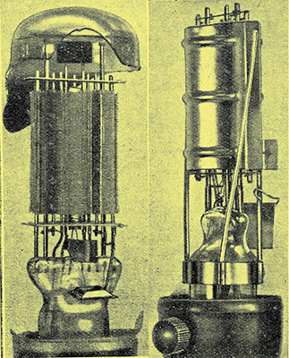
The electrodes of an early output pentode can be seen on the right, and on the left there is a modern large output pentode.
|