|
The Hexode, Heptode and Octode
In this concluding article, frequency-changers are dealt with in considerable detail. The action of such valves is extremely complex and is still the subject of intensive research. No attempt at a complete explanation all the effects is made, therefore, and the second order effects, although important, are dealt with briefly. In conclusion, some effects common to most valves, whatever their number of electrodes, are discussed.
Although the hexode follows the pentode in order of electrodes, it is only recently that it has become widely used, and the heptode preceded it in popularity. It will, therefore, be more convenient to take this seven-electrode valve first.
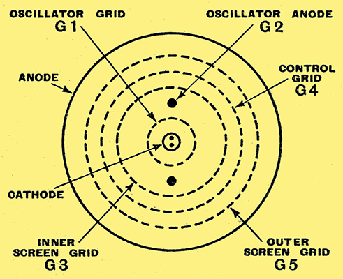
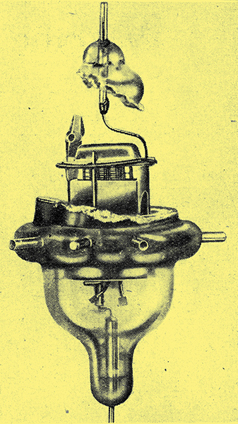
Fig. 15. - The general electrode assembly of a heptode valve is shown here.
The heptode was developed as a frequency-changer and the general arrangement of the electrodes is shown in Fig. 15, and the conventional symbol is given in Fig. 16 with a typical circuit. Grids 1 and 2 are used with the cathode to form a triode oscillator and grid 4 is the control grid to which the input signal is applied. Grids 3 and 5 are screen-grids and are internally connected.The output at intermediate frequency is taken from the anode.
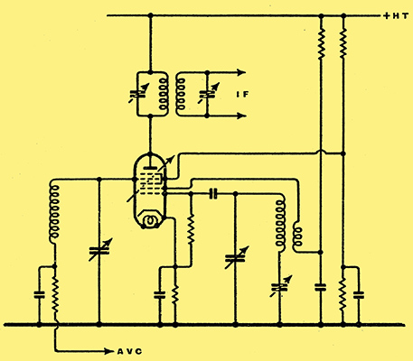
Fig. 16. - This diagram shows a typical circuit for a heptode frequency-changer.
Electrons emitted by the cathode form the usual cathode space-charge. The grid 2 is a grid more in name than in tact, for it is not usually of the normal grid construction but consists often merely of two bars as shown in Fig. 15. It is maintained at a positive potential which is often somewhat higher than that of the screen G3.
In operation G2 and G3 pull electrons through the oscillator grid G1 and the majority pass to G3 or through its meshes. Some go to G2, however, and this electrode forms the anode of a triode. The electrons which land on G3 form the inner screen-grid current, those which pass its meshes from a space-charge between G3 and G4. They do this because once they have passed G3 they come within the repelling influence of the negative grid G4.
The screen space-charge is essentially similar to the cathode space-charge, but its density depends on the number of electrons passing through G3 and hence upon the potential of G1 and, to a lesser degree, upon the potential of G2. Acting through the control grid G4, the positive screen G5 pulls electrons from the screen space-charge and the number depends upon the potential of G4 and upon the density of the space-charge itself. The number of electrons pulled to G5 thus depends primarily on the potentials of G1 and G4.
Some of these electrons land on G5 and constitute the outer screen-grid current; the remainder are attracted to the more positive anode.
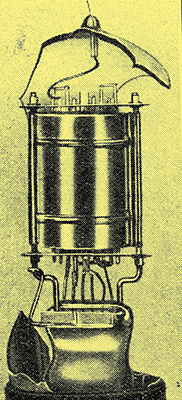
The electrode system of a typical heptode is shown in this photograph.
In normal operation the incoming signal is applied to G4 and the valve is oscillating between G1 and G2, so that there is an oscillator-frequency potential applied to G1. The anode current depends on the potential of both grids, and as the potentials are varying at different rates, beats are formed in the anode circuit. Thus, it the signal has a frequency of 1 MHz, and the oscillator functions at 1.5 MHz. the anode current will have components of 500 kHz and 2.5 MHz. The former is the one usually employed.
Perhaps the simplest way of regarding the operation is to consider G4, G5, and the anode as the electrodes of a conventional tetrode with the space charge outside G3 as cathode. Given a constant space-charge, the operation of these electrodes is essentially the same as that of a tetrode and the same secondary emission defects occur.
Taking this tetrode with the space-charge for cathode, it is easy to see that the electron stream to the anode can be controlled by varying the space-charge density, and this is done by the inner electrodes. The space-charge is controlled by G1 and G3. The other elements, cathode, G1 and G2, form an ordinary triode oscillator.
As the outer electrodes are equivalent to a tetrode, this part of the valve suffers from the usual tetrode defect of a negative portion of the anode-volts anode-current characteristic. This can be remedied in the same way as with a tetrode - by introducing a suppressor-grid G6 between G5 and anode. The valve is then an octode. The heptode is to the octode exactly as the tetrode is to the pentode, and it is consequently unnecessary to discuss the octode further.
Presumably, the heptode could be given octode characteristics in the same way that the latest tetrodes have pentode characteristics, by adopting a similar treatment. So far as the writer is aware, however, this has not been done, probably because the heptode has been largely displaced by the hexode.
The heptode was designed primarily to give an inexpensive frequency-changer with freedom from interaction between the signal- and oscillator frequency circuits. It does this in good measure on the broadcast bands, but on short waves various second order effects become important and the operation is seriously affected.
The inter-electrode capacities, although small, are not negligible, and give coupling between G4 and G1 and between G4 and G2. Secondary electrons are emitted by G3 and collected by G2. One of the greatest drawbacks, however, is the effect of the screen space-charge on the signal grid. As this space-charge fluctuates at oscillator frequency it behaves as an electrode of varying charge and by ordinary electrostatic action causes a current of oscillator frequency to flow in the circuit connected to G4.
As a result of these effects and some others, a considerable degree of interaction between the signal and oscillator circuits exists and the valve is not very suitable for short waves. Considerable development has recently taken place in the octode and some of the latest types are greatly superior. The splitting of the electron stream into definite beams and the adoption of a solid screen for G2 has led to a distinct improvement, while the use of a neutralising circuit between G1 and G4 still further reduces the coupling [★] The Wireless World, May 26th, and June 2nd, 1938.. This neutralising circuit consists of a capacitor and resistance in series and is built into the valve.
The Triode-Hexode
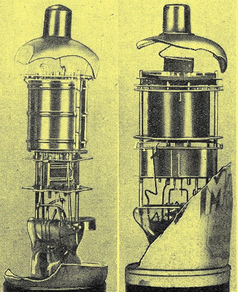
On the left is shown the interior of a triode-hexode, the triode section can be seen below the hexode assembly. A triode-heptode appears on the right.
As an alternative to the heptode and octode, the hexode was developed and is now very widely used. It is usually known as the triode-hexode, because a hexode and a triode are built into the same glass envelope. The triode is used as the oscillator and the hexode as the mixer.
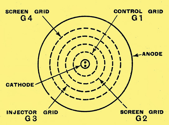
Fig. 17. - The hexode frequency-changer has an electrode arrangement of this form. It is usually included with a separate triode assembly in a common envelope.
The electrode arrangement is sketched in Fig. 17, and it will be seen that the inner grid G1 is now the control grid to which the signal is applied. It is surrounded by a screen-grid G2 at a positive potential. Then comes a second control grid G3, usually called the injector grid because it is fed from the oscillator, and a second screen grid G4. Last of all, there is the anode.
The operation is at first sight not very different from that of the heptode, save that a separate oscillator is needed. However, most of the second order and undesirable effects of the heptode are absent.
The cathode, G1, and G2 together give the usual triode action and the electrons which pass G2 form a space-charge outside it because of the negative grid G3. This space-charge changes in density at signal-frequency. The oscillator amplitude applied to G3 is large and only permits electrons to pass this electrode during a portion of the positive half-cycles. At this time the positive screen G4 pulls the electrons through and those which pass its meshes are attracted by the anode.
Secondary emission from the anode can occur and give rise to a negative resistance kink in the characteristic. In some of the latest types this is overcome by the inclusion of a suppressor grid G5 between G4. and the anode. The valve then becomes a heptode, but of different kind from the ordinary heptode. Confusion does not arise as the valve nearly always has a triode section. As the tetrode is to the pentode, and as the heptode is to the octode, so is the triode hexode to the triode-heptode.
A complete explanation of all the events in complex structures of this nature is beyond the scope of this series of articles. But sufficient has been said to show the general action, and in conclusion it will be sufficient to indicate some general effects common to most types of valve.
Before doing so, a few words about multiple valves may be advisable. These do not differ from the types discussed, save that the electrode assemblies of two or more valves are included in the same glass envelope. A duo-diode-triode, for instance, consists of two diodes and one triode. Each section functions independently of the others and follows the laws governing its own type. In practice, such a valve is not as flexible as the three separate valves which it replaces, for the cathodes are usually connected internally, and there is also the possibility of interaction between the sections through the small capacities existing between them.
Other multiple valves are the duo-triode or Class B valve (two triodes), the QPP valve (two pentodes), the duo-diode (two diodes), the triple-diode (three diodes), the triode-pentode (triode and pentode), the triode-hexode (triode and hexode), the triode-heptode (triode and heptode), duo-diode-pentode (two diodes and pentode); and triple-diode-triode (three diodes and triode).
Of the general effects common to all valves is a change of input capacity with grid bias. This is most important with tetrode and pentode RF and IF amplifiers. If the total capacity between control grid and earth is measured with the valve cold a certain value will be obtained. If it is measured again with the cathode hot, but with sufficient grid bias to cut off anode current, another higher value will be obtained. The increase is due in part to the expansion of the electrodes, but is also caused by the grid-cathode capacity being effectively between grid and the cathode space-charge instead of between the grid and cathode itself.
The cathode space-charge is nearer the grid than the cathode, and so the capacity is greater. If now the grid bias is reduced the input capacity increases because the cathode space-charge tends to move nearer the grid as the anode current increases. The change of capacity may be as much as 5 pF and it naturally affects the tuning of the grid circuit of the valve. This is one reason why it is almost impossible to maintain symmetrical band-pass curves in practice. The grid bias is varied for volume control, either manually or automatically, and the tuning of the circuits consequently varies also to some degree.
A similar effect, but of rather more complicated nature, occurs in frequency-changers and is especially bad, since it causes a change in oscillator frequency. With some of the latest valves it is kept at a very low level.
On short waves an additional effect occurs. The time taken for electrons to pass through the valve is no longer negligible compared with one cycle of the input signal. The conditions in the valve are then rather different from those described earlier. If the grid voltage is changed there is a time lag before the resulting change of anode current takes place.
Suppose, for instance, that the grid voltage is changed negatively with extreme rapidity. The negative grid repels many of the electrons which were previously approaching it, and turns them back to the cathode. At the same time, the electrons which had just passed the grid are still receding from it, for they have not yet had time to reach the screen or anode. There are, therefore, more electrons receding from the grid than there are approaching it. Through ordinary electrostatic action this results in an electron flow or current to the grid in the external circuit. The action is just the reverse if the change of grid voltage is in the opposite direction.
The grid current absorbs power from the input circuit and the valve is said to have an input resistance. The value of this resistance is such that if connected across the input of a perfect valve it would absorb the same power as the practical and imperfect valve. The value of the resistance is proportional to the square of wavelength and can usually be ignored above some 20 metres. At 5 metres, however, it may be 2,000 Ω or less.
This illustration clearly shows the interior of an acorn pentode. It is shown here much larger than life!
It seriously limits the performance of a valve on short waves, and it is possible greatly to increase the input resistance by reducing the distance between the electrodes. The acorn valves are examples of such action and are very successful. They are not popular, however, because the clearances are so small that they are difficult to manufacture, and compared with ordinary valves they are rather fragile.
It has recently been found that the inductance of the internal connections of the valve also leads to a low input resistance at high frequencies. The low input resistance of the ordinary valve is thus not entirely due to electron transit time effects, but is partly caused by feed-back effects due to the impedance of its internal leads, particularly the cathode lead.
There is consequently a general tendency to adopt smaller valves with bases which lend themselves to the attainment of short internal connections. Some of the latest valves show a considerable improvement over the older types and have an input resistance which, while lower than that of the acorns, is high enough to permit the attainment of good results down to about 5 metres (60 MHz) or even lower.
|