|
This material has been extracted from part three of 'The Home Laboratory' series.
In proclaiming the desirability of the cathode-ray tube the writer is handicapped by not being a poet, who alone could handle the subject adequately. Mere prose may convey the impression that a cathode-ray tube is just another piece of equipment, and that there is room for difference of opinion concerning whether or not it is worth having. That would be a great mistake. It is very questionable whether any establishment without, a cathode-ray tube is entitled to be called a radio laboratory.
Another great mistake is to suppose that it is expensive. The idea may still survive that, first, the tube itself costs £10 to £15; secondly, that it cannot be worked without thousands of expensive and dangerous volts; and, thirdly, that even then it is not much use without one and possibly two time-base units, each with from three to six unusually high-priced valves and perhaps sundry amplifiers, modulated oscillators, etc. While this may be true of television and certain special laboratory applications, it is certainly quite wrong so far as general laboratory work is concerned. Cathode-ray tubes can be bought for about 35s. upwards.
Some Comparisons
Now that illusions concerning the advantages and benefits of cathode-ray oscillography being beyond the amateur of moderate means have been removed, these advantages can be examined without the bitterness of envy. As regards the impedance the cathode-ray tube is strictly comparable to the valve voltmeter; as regards frequency range, not all types extend so, far as a well-designed valve voltmeter. But whereas a cathode-ray tube can do all or most of the things a valve voltmeter does, that is only quite an insignificant part of its capabilities. Valve voltmeters, and other sorts of meters, are restricted to one dimension, such as voltage or current. A cathode-ray tube responds to two or even three dimensions simultaneously. And whereas meters give static readings and are useless for examining even quite slow movements, the cathode-ray tube traces variations at the speed of radio frequencies.
Mere statement of these two derestrictions can hardly be expected to reveal the extraordinary range of usefulness they open up. Books have been written on the subject, but they include only a selection of the possibilities. So useful are cathode-ray methods that people who work at other things, such as mechanical engineering and medicine, convert what they are studying into electrical form just in order to be able to bring the cathode-ray tube to bear on the problem. It is an under-statement to say that the cathode-ray tube occupies as important a place in the radio engineerbs work as the X-ray tube does in the surgeonbs.
A meter shows merely the magnitude of the voltage or other quantity measured, the cathode-ray tube is capable of showing (simultaneously, if necessary) the magnitude, form, phase, and frequency of a wave, and its relationship to other quantities. And, unlike most meters, it does not matter how violently the 'pointer' is treated.
Where Other Methods Fail
Suppose one has a 'quality' amplifier that does not quite live up to its name. According to meter readings everything seems normal. And at low or moderate volume it sounds all right; but the output before noticeable distortion sets in is disappointing. Without a cathode-ray tube one is in the dark; with it, the amplifier can be thoroughly checked in a very short time. Perhaps spurious oscillation of the output valves takes place during a portion of the signal cycle when it exceeds a certain amplitude. Or the transformer iron may be saturating at low frequencies. Or the low frequencies may be modulating the high. All sorts of unexpected distortions come to light when an amplifier is subjected to cathode-ray tube examination. Even when tests can be done in other ways these are generally much slower or more difficult.
For a detailed account of the theory and construction of the cathode-ray tube a whole book is needed, [★] See the references below but before discussing the choice of tube and equipment it may be as well to refer very briefly to the essential features, and how they differ between one type and another. It may be thought of as a specialised form of valve; there is the cathode, directly or indirectly heated, as a source of electrons; then the anode, to which a high positive voltage is applied, holds out a very powerful attraction to these electrons, but is tantalisingly kept out of their reach by means of the counterpart of a valve's grid - a cylinder which is connected to a negative bias, constraining them into a narrow stream so that they pass through a hole prepared for them in the anode, and continuing by their own momentum they strike a chemical screen at the far end of the tube with such violence as to cause a visible glow.
This narrow electron ray, after it has emerged from the anode, can be deflected from its course by either electric or magnetic fields, so causing the spot of light to move over the screen; and the magnitude, direction, and change with time of such fields made plain to see. Although all sorts of elaborate patterns or figures can be caused to appear in this way, it must be clearly realised that these are optical illusions caused by the 'visual persistence' of the eye, aided to a greater or lesser extent by a similar characteristic of the screen itself. At any one instant only a single spot of the screen is being touched by the ray.
The fineness of the spot is a most important characteristic of the tube, because it determines the amount of detail that can be revealed on a screen of given size. One pays much more for a larger screen, and if the size of the spot increases in proportion there is no advantage at all except in the distance at which the results can been seen. While this is important for demonstrations, it is generally of no interest in the laboratory. Quite the contrary, in fact, for the larger screen generally necessitates a greater deflecting signal if the size of the spot is in proportion; a small screen is therefore to be preferred if the spot is correspondingly small.
Methods of Focusing
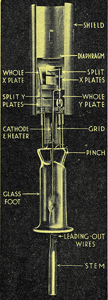 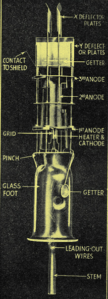
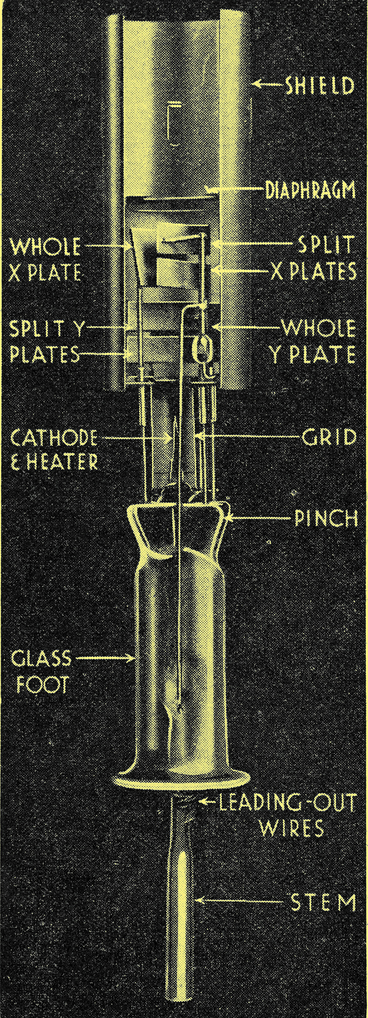
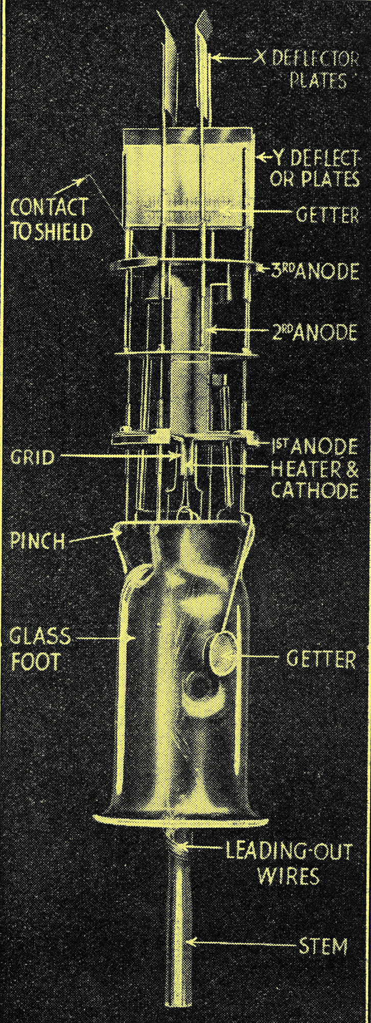
(left) Fig. 1. A gas-focused cathode-ray tube, showing a section of the electrode system. The split deflector plates form part of a system for avoiding origin distortion. (right) Fig. 2. Section of electrode system of a high-vacuum tube with electrostatic focusing and deflection.
The smallness of spot is important, then, for more than one reason. To attain it, the focusing effect of the cylinder (or grid, if valve nomenclature is followed), is not enough. Tubes are classified principally according to the method of focusing, into gas-focused and high-vacuum types, and the latter subdivided into electrostatic and magnetic varieties. In gas-focused. tubes (Fig. 1) there is only a partial vacuum; sufficient gas is present for the ray to cause a measure of ionisation along its path, which has the effect of drawing the scattering electrons into a narrow beam. This type of tube is simple to work; gives good results with low anode voltages; and is not seriously defocused by unbalanced signal circuits (one side 'earthy'), but begins to lose focus when the spot velocity corresponds to a frequency of deflection exceeding some hundreds of kHz (but oddly enough regains it at ultra-high frequencies); there is non-linearity of deflection near the central position of the spot (known as origin distortion); modulation of the spot's brightness (as in television) is not practicable; and only tubes with directly heated cathodes are obtainable.
In the electrostatically focused high-vacuum tube (Fig. 2) there are two or even three anodes at various stages along the tube, and these are maintained at voltages so graduated as to make the beam converge on the screen. The system is described as an electron lens because it is in some ways analogous to an optical lens. To secure satisfactory results this rather complicated electrode system must be located with some precision; but if the beam is magnetically focused by means of steady current passing through a coil wound around the axis of the tube externally, the construction of the interior parts of the tube is simplified, and there is more scope for placing internal deflecting plates. It is also claimed that a bigger beam can be focused, giving a brighter spot. While magnetic focusing is on the increase, it is at present generally confined to television use.
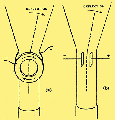
Fig. 3. Simplified diagrams showing the action of (a) magnetic deflection and (b) electrostatic deflection of a cathode beam.
A properly focused 'pointer' having been obtained, the next thing is means for deflection. Unlike a meter pointer the cathode-ray can be deflected in two or more directions at once, thus enabling, for example, the input and output of an amplifier to be directly compared. Nearly all tubes for laboratory purposes are provided with two pairs of electrostatic deflecting plates, distinguished as the X and Y pairs (corresponding to the X and Y axes of a graph). Magnetic deflection is possible, alternatively or additionally, by means of external coils around the neck of the tube with their axes at right angles to it. These coils are not so generally useful, because appreciable power is required to produce deflection, and their inductance is likely to cause difficulty except at low frequencies. To ensure a uniform deflecting field a pair of coils is placed as shown in Fig. 3 and deflection takes place in a direction at right angles to the common axis of the coils. Electrostatic deflection, however, is in the same plane as a line joining the plates. Whereas electrostatic deflection is inversely proportional to the anode voltage, magnetic deflection is inversely proportional to the square root of the anode voltage.
In selecting a tube there are quite a large number of points to be considered. For audio and low radio frequencies the gas-focused type is probably the most suitable. Origin distortion can be removed, where necessary, by biasing the deflecting plates; and certain Cossor tubes are provided with split plates to enable this bias to be applied without deflecting the spot (Fig. 1). Incidentally, there is no origin distortion With magnetic deflection. If work at high radio frequencies - 1 MHz and upwards - is to be done, the high-vacuum type must be used. An advantage of the vacuum tube is that if signals are applied to the control grid they vary the brightness of the spot without defocusing it, so giving a sort of additional dimension to play about with. Actually it is not so very useful outside television.
The deflection sensitivity of either gas or vacuum types is of the order of 400/V millimetres per volt, where, V is the anode voltage. At this figure, if 400 Volts are applied to the anode, a voltage of about 25 between the deflector plates gives a deflection of one inch, and a peak alternating voltage of the same amount draws a line two inches long. It is important to realise that the deflection sensitivities of X and Y plates are not necessarily the same; in a very short tube such as the miniature RCA.Type 913 the difference is quite large.
The maximum anode voltage for which the tube is rated - usually several thousands - thus requires a considerable deflecting voltage to give a reasonable-sized figure on the screen. And great care must be taken not to let the spot rest stationary on the screen, for it will quickly 'burn' it and cause permanent loss of fluorescence. The life of the cathode is also reduced by high anode voltage. So there is obviously no sense in using the rated voltage unless strictly necessary; and, fortunately, it is only for special work (such as photographing transient figures or very high-frequency deflection) that it is necessary. For general use a few hundred volts gives a figure visible in a not-too-bright room, and there are the advantages of relatively high deflection sensitivity and long life. The greater the length of tube, the greater the deflection sensitivity, obviously; but to gain the full advantage of a long tube it is necessary for the focusing to be of a correspondingly high accuracy.
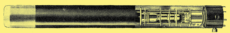
Fig. 4. Cossor 2 inch tubular high-vacuum cathode-ray tube.
There is a Cossor tube 18in. long (Fig. 4), and although the screen diameter of 2 in seems small in proportion, extremely fine oscillograms can be photographed, and for a full-sized figure a peak signal of only 30 Volts is needed.
An important characteristic, more especially at high frequencies, is the signal output impedance. One of the advantages of electrostatic deflection is that this impedance is so high that the effect on the signal circuit may often be neglected. The capacity of any deflector plate to all other electrodes is similar to that of a valve's control grid - about 5 to 12 pF - and the resistance, even in gas-focused tubes, is almost infinite.
Screen Colours
Various types of screen are available, some being particularly suitable for visual work and others for photographic; the former generally give a green light and the latter blue, but this is not invariable. The time taken for the fluorescence of the screen to disappear after the ray has moved from it may be anything from a fraction of a micro-second to half a minute; it is thus possible to get special screens for work involving exceptionally fast or slow deflections.
References
- The Cathode Ray Oscillograph in Radio Research. Watson-Watt, Herd, & Bainbridge-Bell. H M Stationery Office.
- The Low Voltage Cathode-Ray Tube. G Parr. Chapman & Hall.
- The Cathode Ray Tube at Work. John F Rider. For American practice.
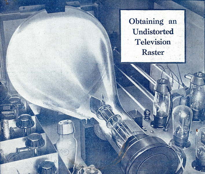
Front cover picture from April 28, 1938 showing an electrostatically deflected tube of the time.
|