|
An explanation of the cause of image area distortion and astigmatism in cathode-ray tubes, with suggestions for over coming these defects.
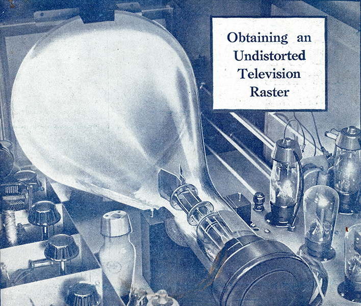
Original front cover picture showing an electrostatically deflected tube of the time.
At first sight the problems connected with the electrostatic deflection of a beam of cathode rays would appear to be capable of solution by means of very simple circuits. That these problems are, in fact, not easily solved has become increasingly apparent as the cathode-ray tube has been developed.
As is often the case, the elimination of one fault in the cathode-ray tube has brought to light others which were previously masked by still greater faults. The change from gas focused to high-vacuum tubes and the gradual development of the latter has made it obvious that the application of an asymmetric deflection potential, whether AC, DC or a mixture of both, is unsatisfactory in the majority of cases, e.g., where the amplitude of deflection is more than about10% of the screen diameter.
The circuit arrangement adopted for asymmetric application of the deflecting potentials is shown in Fig. 1. When two deflecting systems are arranged so that they lie mutually at right angles to one another, and in such a manner that one pair of deflectors is nearer to the fluorescent screen than the other, a change of mean potential of the pair nearer to the screen modulates the sensitivity of the other pair. The arrangement behaves as though the velocity of the electrons in the beam between the plates nearer to the anode was modulated by the variation of mean potential of the other pair. A change of mean potential necessarily occurs in an asymmetric system since one plate of a pair is constantly varying in potential, the voltage on the other plate remaining fixed. The deflecting sensitivity of a pair of deflectors in a cathode-ray tube is equal to K/V where K is a constant depending on the geometry of the tube, and V is the potential through which the electrons have fallen. Thus. in order to determine the sensitivity of the pair of plates further from the screen, a factor dependent upon the instantaneous effective potential on the live deflector nearest to the screen must be added to the voltage of the final anode in order to obtain the correct value for V.
The foregoing, remarks will be more easily appreciated if it is borne in mind that the electrons forming the beam are controlled by the electric fields through which they pass, and these fields control the velocity of the beam in the plane of the field concerned. Hence, the beam of electrons attains various velocities in different parts of the tube. Electron velocity is usually expressed in 'equivalent volts', the appropriate voltage at any point in the path of the beam being that through which the electron has fallen on its passage from the cathode, Thus, if there is a difference of potential of 5,000 Volts between the final anode and the cathode, the electron velocity at the anode is expressed as being 5,000 Volts. The electrostatic deflectional sensitivity is inversely proportional to the square of the electron velocity at the point at which the deflecting field is applied, it being, of course, understood that the deflecting field appears at right angles to the direction of motion of the beam.
Influence of Various Fields
The velocity of the beam at any one point along its length is actually a compound one, due to the original radial velocity acquired by the electrons when emitted from the cathode, the sum of the longitudinal velocities due to the various accelerating fields existing between the focusing electrodes and the transverse fields produced by the potentials applied to the deflectors.
There are also several minor fields which still further complicate the force acting on the beam; the more or less longitudinal decelerating field due to the charge acquired by the fluorescent screen by electron bombardment, the fields produced by charges on the surface of the glass together with that due to the presence of. secondary electrons emitted from the screen, and, finally, the radial field due to mutual repulsion of the electrons forming the beam.
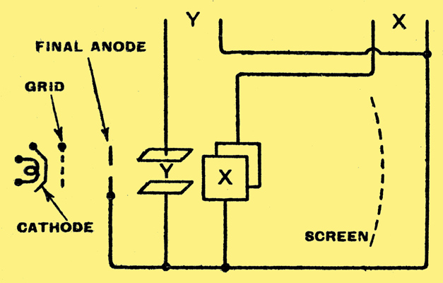
Fig. 1. Asymmetrical connection of two pairs of deflector plates.
When two pairs of deflectors are connected asymmetrically, as shown in Fig. 1, and fed with two DC potentials which may be separately varied, the resultant area of the image will be like a quarter of a trapezium. Fig. 2 will make this clear. Assume that the potentials on the two deflectors X.and Y maybe varied trom 0 to 100 Volts positive with respect to the potential of the anode to which the other two deflectors are connected. Let (b) denote the position of the spot when deflector Y is at a potential of 100 Volts and X at zero potential. If Y remains at 100 Volts positive and the same potential is applied to X the spot will move to position (c). Note that the distance (cd) is less than the distance (ab), because the sensitivity of the Y deflector has been reduced due to the potential on X. If, now the potential on Y be reduced to zero, leaving that on X at 100 Volts positive, the spot will move to position (d). Upon removing the voltage from the X deflector the spot returns to position (a).
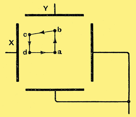
Fig. 2. Deflection of the beam by the arrangement of Fig. 1.
If the circuit is arranged so that the plates are fed with AC potentials (the potential on Y being at a higher frequency than that on X), thus causing the X and Y deflectors each to become alternately positive and negative to a peak potential of, say, 100 Volts, then the area covered by the image is as shown in Fig. 3, i.e., a complete trapezium. It should be noted that the long edge of the trapezium lies adjacent to that X plate which is connected to the final anode of the tube.
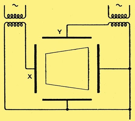
Fig. 3. Shape of the area covered by the image with alternating deflecting potentials.
The use of these simple asymmetric deflecting systems also introduces, at least theoretically, two forms of distortion of the spot on the screen; an enlargement ot the spot and astigmatism, or drawing out of the spot into a line in the direction of the deflection.
It should be clear from the foregoing remarks that trapezium distortion is due to the fact that the mean potential between the deflectors is not constant with respect to the final anode of the electron lens system.
The mean potential can obviously be kept constant by applying the deflection in a symmetrical manner to both plates of each pair, but the word 'symmetrical' requires to be accepted in its literal sense. This means that the two potentials must be equal at every instant or, alternatively, that their algebraic sum must be constant.
Unfortunately, however, the above considerations, while sufficient to avoid trapezium distortion, are not enough to ensure the best results, as astigmatism must also be avoided. It is, therefore, further necessary to arrange that the mean potentials between each pair of deflectors and the anode are not only constant, but that they remain fixed at specific values.
Astigmatism has the same meaning in electron-optics as in light-optics, i.e., it denotes the condition existing when one obtains good focus in one direction and lack of focus in a direction at right angles to the first. Astigmatism may be introduced by certain transverse fields, and especially by any misalignment of the electrodes forming the electron lens system. Furthermore, asymmetry of position of the deflectors with respect to the hole in the final anode is a serious cause of defocusing of the spot.
The amount of error in electrode alignment which can produce astigmatism in a cathode-ray spot is so small that the majority of tubes supplied by any factory show some signs of this defect. For this reason it is advantageous to be able to correct astigmatism in the circuits external to the tube. To this effect, it is only necessary to arrange that the mean potential between each pair of deflector plates and the final anode may be separately adjusted. By this means, we introduce, two variable cylindrical lenses at right angles to one another which can be adjusted so as to neutralise the effective cylindrical lens action introduced by small displacements of the electrode system from true alignment.
The necessity for adjustment of the mean potential of each pair of deflectors to a fixed value with respect to that of the final anode is unfortunate since it adds to the complexity of the associated circuit, but, where large deflections are required, the resulting improvement in focus is generally appreciable. The potential required for this purpose varies with different tubes even though they are made to the same design. Fig. 4 shows one method of arranging the circuit to provide means of adjustment.
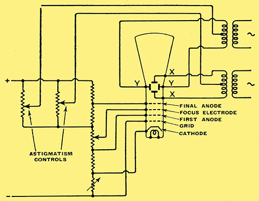
Fig. 4. Method of correcting for astigmatism.
In conclusion, the following details must receive meticulous attention if the cathode-ray tube is to provide good focus all over the screen and if trapezium distortion is to be avoided.
Details connected with the manufacture of the tube:-
- The beam must be circular in cross-section.
- All the electrons in the beam must pass a given point with the same longitudinal velocity.
- All the fields through which the beam passes must be homogenous
- The electrode structure should be in perfect alignment.
- The electrode apertures must be perfectly circular
Details connected with the use of the tube:-
- Except for very small deflections the two deflecting potentials must be symmetrically applied, and, finally
- The mean potentials of the two pairs of deflectors should be constant and should bear definite but unspecified relationships to the potential of the final anode.
|