I'm currently working on a long-term project for which l needed a double-ended screened grid valve with an uncommon filament voltage. It took me some months to track one down but I did eventually obtain a working sample of the Cossor SG210 required. I am most grateful to those whose kind help enabled me to achieve this. They along with others, are acknowledged at the end of this article.
This experience started me thinking that there must be vintage receivers around that could be rendered working but for the want of a good double-ended screened grid valve. As l discovered, these valves are not easily obtainable and there are a number of possible reasons why using an original vintage sample may not be seen as the best solution e.g.:
It seemed to me that a suitable substitute for these valves this might be a good thing. So this article is about my quest for such a substitute and the achievement of what I believe is an acceptable outcome.
By 1927 half of domestic wireless receivers were crystal sets, the other halt were of course valve sets and the situation was developing rapidly. Valve technology had advanced, bringing improvements in filaments and the hardness of the vacuum within the envelope. Valves were available in different types to suit the various stages within a receiver e.g. Loudspeaker, AF amplifier, Detector and HF amplifier. Not only that but the new dull emitter types with oxide coated filaments were also offered in 2, 4 and 6 Volt versions.
Yes, valves abounded - and they were almost all triodes. There were some four-electrode valves: however. these had limited application in specialised circuits e.g. with a low HT supply, using reflex circuits or as a mixer in one of the relatively rare superhets of the time.
The problem with Triodes is that they are poor HF amplifiers (unless you use them in grounded-grid mode, which just wasn't done then). This, as is well known, is due to the internal capacitance that exists between anode and grid. It causes instability and oscillation when you try to get any useful amount of HF amplification out of the valve. The existing four-electrode valves didn't help either because they had not been designed with this problem in mind.
In 1924, Professor L A Hazeltine had developed his Neutrodyne circuit using 'Anode Neutralization', which when correctly balanced, externally neutrallsed the effects of the grid-anode capacitance. This allowed a reasonable amount of stable HF amplification. It was very popular in America but less so in Britain. One can speculate on the reasons for this but although the circuit often appeared in designs for home construction (most notably the Wireless World Everyman Four) the simple fact is that this technique did not catch on here to the same degree.
Thus the typical receiver of the day was composed of a large aerial and tuned circuit connected to the most sensitive type of detector, which was a Leaky Grid Detector with reaction. If the set was intended for loudspeaker use this was usually followed by two (or more) valves acting as AF amplifiers. These sets gave good results on strong signals but did not perform well if the signal was weak, as was often the case with distant or foreign stations. Even the most sensitive detector needs a reasonable signal (about 100 mV) to perform effectively.
Then in late 1927 something happened which was to revolutionise wireless reception. The Marconi-Osram Valve Company released upon a justly grateful world the S625. This valve, designed by Captain H J Round, was the first generally available Screened Grid valve.
If you used this new valve and followed some simple rules on circuit design and layout, you could easily achieve a very useful amount of stable HF gain. Reception was louder and if desired. a smaller aerial could be used. However the greatest benefit was that weaker signals and distant stations could be received.
Of course it was the additional screening grid, forming an electrostatic screen between the anode and control grid, which gave the valve its name. When connected to an 'earthy' supply it almost entirely negated the effects of the anode-grid capacitance.
It was said that a receiver fitted with one of these valves would give the same performance as a set having two neutralised triode stages.
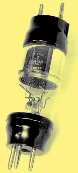
Fig, 1 shows an S625 the circular screening grid can be clearly seen adjacent to the normal grid and filament assembly. The anode is not visible. being concealed by the screen's flanged edge and the silvery gettering on the inside of the glass bulb. There are two valve 'bases' because it is desirable to keep the grid and anode connections widely separated. There is no point in eliminating the internal feedback if you don't also remove the possibility of external coupling.
The new valve was used in a number of commercially produced receivers, examples of which can be seen in Jonathan Hill's Radio! Radio! (pages 90 to 92 in the 3rd edition). It also featured in designs in home construction magazines (e.g. 'A Three for the new valve', designer - Percy Harris, The Wireless Constructor November 1927). In addition there must have been a number of successful sets 'designed' and built by some of the more able home experimenters. It's not possible to say how many sets were made for this valve but the number could not have been great because the S625 had a short reign.
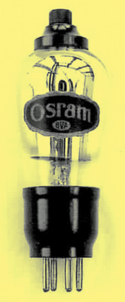
Before the end of the following year (1928) this magnificent valve had been superseded by the slightly more magnificent S215. More magnificent because it had a better and more economical performance, but perhaps it is less charming than this quirky looking valve with its two valve bases? The same fate befell all double-ended SGs with all the major manufacturers producing at least one single-ended version. Fig. 2 shows the typical form taken by the double-ended SG's successors.
The new single-ended design was to become the standard form, which was maintained through all the subsequent stages of development. i.e. metallised bulbs, variable-μ and then on to RF pentodes, the only 'improvement' was to replace the 5 BA screw top with a metal cap in 1933.
The Survivors
As far as I know, most of the surviving double-ended screened grid valves are not in sets. but in valve collections and it could be argued that those which are still working should not have their remaining useful life used up by operating sets. Therefore a suitable substitute might be useful.
What is a Suitable Substitute?
A good question. For me it would have to meet the following criteria:
- be mechanically and electrically compatible
- produce the same or a similar performance in a receiver
- have a similar appearance and not look 'alien' when in a receiver.
From this it is clear that such a device will have to be designed and made as it does not (so far as I know) already exist.
For the amateur the last of the three criteria, the cosmetic aspect, is the most difficult to achieve. However this is made easier by the tact that both of the valve 'bases' required are the same as a standard British 4-pin base (B4) but with some oi the pins removed. So it's just the bit in the middle that has to be worked at.
The obvious way forward is to use another valve as the basis for this device. I could now list the various candidates and debate their merits but life's too short for that. so I'll cut straight to the chosen solution.
The Design Solution
The valve chosen was the Mullard DF91, commonly Found in post-war personal portables, which run on dry batteries. It has a number of useful features in that it:
- is an HF amplifier
- is small
- is available
- requires no supplies which are greater than those for the original valves
- has suitable values of mutual conductance and anode impedance.
The two obvious differences are that it is a pentode not a tetrode and it is variable-μ. For the range of conditions under which the valve will be operated these factors have no appreciable impact on its suitability as a substitute. Table 1 below compares the relevant characteristics of the DF91 with those of the MOV S625 and Cossor SG210.
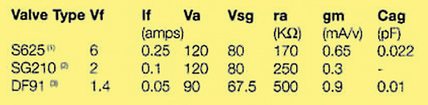
Table 1
Notes
- All figures from History of the British Radio valve to 1940 author Keith Thrower OBE.
- All figures from manufacturers' data except ra and gm, which are from the above book.
- All figures from manufacturers' data.
Working through the table, we can see that we need to lose some volts for the filament, anode and screen grid feeds. This we can do.
The filament current requirement is smaller so that's no problem. No problem that is providing you don't want to use an existing filament rheostat to adjust HF gain by 'filament dimming' as its value will be too low to be very effective with the reduced filament current. Filament dimming is not a good practice and would be slow death to the oxide coated filament of a DF91. Gerry Wells summed it up aptly when he said, 'it's a very effective way of ruining a perfectly good valve'.
The anode impedance is higher but this should make no noticeable difference to the performance of the receiver unless the coils are very low loss when a slight improvement in selectivity and gain might be noticed.
Mutual conductance is slightly high but of the right order. It can be reduced by running the screening grid at a lower voltage. This was quite a common practice for adjusting HF gain in screened grid valves prior to their being availability in variable-mu versions.
The anode-to-grid capacitance for the SG210 is not known; but is likely to be similar to that of the S625. The figure for the DF91 is lower and therefore again not a problem.
Achieving Electronic Compatibility
Plainly some additional circuitry is necessary to make the DF91 plug-in compatible. The filament will draw a constant current and a series resistor of suitable value in the positive filament lead will meet this requirement.
The current is low (50 mA) so the additional heat generated, even for the 6 Volt version, will only be 230 mW. This factor does need to be considered, as all the additional circuitry must be contained with the DF9l in the final package.
A fixed voltage drop of 30 Volts is needed for the anode feed. However the anode current could vary for different sets. This is because the original valves, although often operated with 0 Volts grid bias, were sometimes used with a bias of up to -1.5 Volts. As the anode current is unpredictable a resistor is not the best choice so a miniature 30 Volt Zener diode was used here. The same approach was used for the screen grid feed and both Zener diodes were bypassed with sub-miniature 0.1 μF ceramic capacitors. This was not so much for decoupling purposes but rather to suppress any noise which might be generated in the diode junctions.
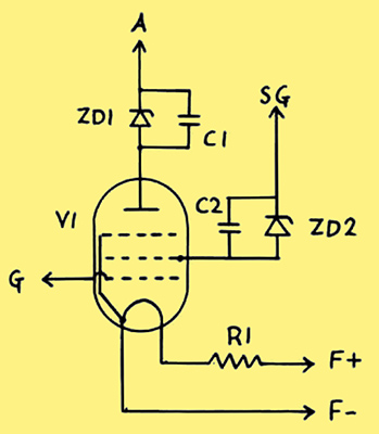
Flg. 3 - The circuit diagram shows the additional components used with the DF91 to enable electronic compatibility to be achieved. The component values for various versions are given in table 2.
The circuit diagram is shown in figure 3 and table 2 gives the component values for 3 versions of the 'new valve' having 2, 4 and 6 Volt filament supplies. For convenience l have given each of these a type number following the normal convention. The value of ZD2 in the S605 (6 volt version) results in the screen voltage on the DF91 being slightly higher than the other versions. This is to take account of the higher mutual conductance in the S625, for which it can be substituted.
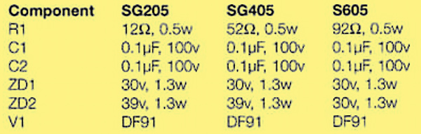
Table 2 - Component values for 3 versions of the 'new valve'. able 2.
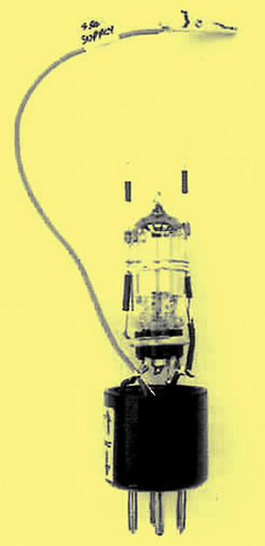
Fig. 4 - Here is shown one of the prototypes, the wires projecting above the top of the DF91 are the screen grid and anode connections.
Fig. 4 shows one of the later prototypes, which is based on the circuit in fig. 3, it was used to check characteristics and measure mutual conductance for various values of screen voltage. Despite its crudity this prototype produces stable HF amplification when installed in a receiver in place of the normal screened grid valve.
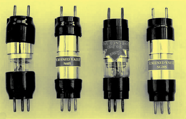
Fig. 5 - Shown first and third in the line-up are original screen grid valves i.e. Osram S625 and Cossor SG210. Their substitutes S605 and SG205 are in positions 2 and 4.
A certain leap of the imagination is required to bridge the gap from this crude prototype to the finished result illustrated in fig. 5. Here two substitutes, S605 and SG205. are shown alongside the original valves. S625 and SG210, which they can be used to replace. The S625 shown is of the long-base type as opposed to the short-base version shown in fig. 1.
Making the New Valves
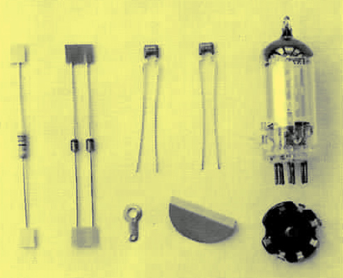
Fig. 6 - These are the parts used to make the internal assembly for the bnew valveb. The only difference between the various versions is in the value of the resistor and one of the Zener diodes.
The parts used to make the internal assembly are shown in fig. 6. In addition to the DF91, the components and valve base, there ls a small copper screen. This is soldered to the underside of the valve base as an electrostatic shield between the anode pin and any grid circuitry in the receiver.
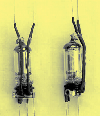
Fig. 7 -
Fig. 7 gives two views of the completed internal assembly. All wires which are not connected to the negative and of the filament, are insulated with heat-shrink sleeving.
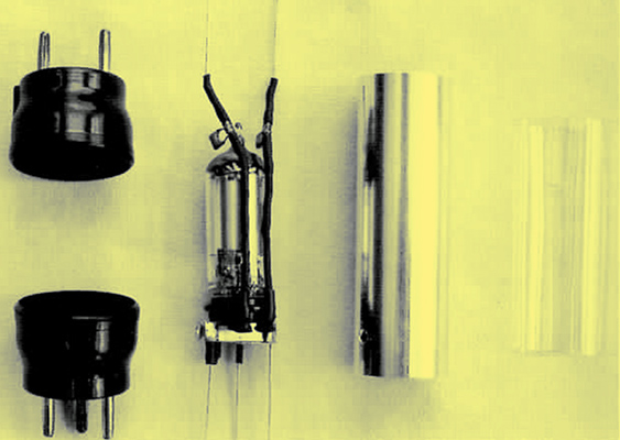
Fig. 8 - These are the main parts used for the final assembly.There are aIso some cosmetic pieces to be added e.g. to simulate the gettering and a label, they serve the additional function of concealing the innards.
The main pans needed for the final assembly are laid out in fig. 8. The aluminium tube forms both the main body of the finished device and an electrostatic screen for the wire that connects the DF91 anode to the anode pin on the top valve base. It ls joined to the copper screen by a pop-rivet and solder tag.
The 'glass envelope' shown to the right is in fact a sheet of transparent plastic curled into a cylinder with the assistance of an electric heat gun.
It is necessary to add some cosmetic improvements before completion in order to produce an acceptable result. Two strips of thin card are wound around the aluminium tube followed by a layer of aluminium kitchen foil to simulate the gettering. Then the 'glass envelope' is added. These parts are all held in place by backing each of them, at the point of contact. with high tack double-sided tape (this is a very fiddly operation).
Now the valve bases can be added. The bases were taken from valves which were useless for any other purpose. They were common valve types with open circuit or very low emission filaments and of no value for display purposes.
In the mark 1 version there were additional mechanical parts and the whole was held together by over a dozen 6 BA screws. It was very time consuming, involving lots of drilling and tapping. Clearly some value engineering techniques needed to be brought to bear and my revised strategy can be summed up as - less screwing, more glueing. The solution was found (no pun intended) in a pack of Araldite Rapid.
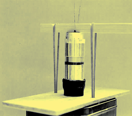
Fig. 9 - Here is a part complete S605 sitting in the glueing jig, wailing for time to take its effect on the Araldite.
The original valves back in 1927 were glued together so this approach seems quite valid. The disadvantage is of course that it there is any kind of internal failure for any reason then the device cannot be repaired. However the same applies to the real thing. In figure 9, a half assembled S605 can be seen sitting in the glueing jig. Although Araldite is quite viscous it does tend to give in to the force of gravity where it is being used for gap filling, so although it takes longer I glued one end at a time.
The last operation is to put on the labels. The masters for these were produced on an ordinary desktop computer using Word Table. They were printed out with white lettering on a black background and my local stationers copied them on a colour photocopier, substituting an appropriate colour for the black. The labels are attached with high tack double-sided tape.
Testing
Each of the 'new valves' was of course tested before final assembly for the reasons already given. However it was also necessary to demonstrate that these substitutes do give a similar performance to the valves that they can replace.
Readings were taken for the S605 and SG205 substitutes and the results plotted against those for the original valves. The characteristic curve most often shown for a screen grid valve is that of la/Va (anode current against anode voltage) with the control grid and screen potentials fixed. l think this is because the curve has an interesting shape due to the negative resistance kink in the middle. However this information is of no practical value if you are going to use the valve for its intended purpose as HF amplifier.
The kink appears when the anode potential drops below that of the screen and although this is relevant in non-standard applications such as a dynatron oscillator, it has no bearing when the valve is used under normal operating conditions.
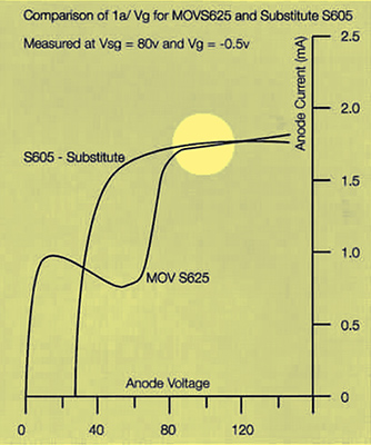
Fig. 10 - The pentode curve of the S605 substitute appears very different from that of the classic tetrode curve exhibited by the original S625. However over the normal range of anode voltage (indicated by the circle) they are extremely similar.
Nonetheless, far be it for me to flout tradition. So reference to Fig. 10 shows the la/Va curve for the new S605 and an original S625. As expected. the S625 shows the characteristic kink and the S605. being a pentode, does not. The point is of course that over the normal range of anode voltage, indicated by the circle on the graph, their characteristics are very similar.
If accurate readings are taken of the anode current with a sensitive meter the figures can be used to calculate anode impedance. This was done and these figures are given (within 10%) in table 3 that shows the key characteristics.
The most useful curve when considering a valve as a conventional amplifier is that of IaVg, as the slope of the curve represents the mutual conductance, in mA/Volt. Fig. 11a compares an original MOV S625 with its S605 substitute and figure 11b shows a Cossor SG210 in relation to its SG205 substitute.


Fig. 11a & 11b - The curves demonstrate that original and substitute are vary similar although in both cases the bnew valveb is slightly better.
The Osram S625 that I have has only about 80% emission so the curve for this valve, shown in figure 11a was plotted using data recorded in 1927 from an early S625. The S605 curve is based on measurements which I made of the device I produced. The anode current is very similar although interestingly the slope for the original shows that its mutual conductance is somewhat lower than that quoted by the manufacturer.
In figure 11b both curves were plotted from measurements made by myself. The anode current and mutual conductance tor the S6205 substitute are a little higher than those for the original valve. It the additional gain is not wanted then lowering the screen grid voltage to say 70 Volts will reduced both of these figures. I think this is legitimate. as the manufacturer's data sheet suggests adjusting the screen voltage in order to achieve best results.
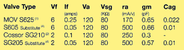
Table 3. Comparison of characteristics for original and 'new' valves.
Notes
- All figures from History of the British Radio Valve to 1940 - author Keith Thrower OBE.
- All figures from manufacturers' data except ra and gm which are from the above book.
- All figures measured except Cag, which is from manufacturers data.
The figures in this table would appear to confirm the suitability of these substitutes.
So Does It Work?
Well yes. When you put it in a set and switch on you get stable HF amplification, with about the same amount of gain that you'd expect from a double-ended screened grid valve. The set works normally.
Yes of course it works, the science tells us it must work. However on a personal level I must confess to feeling a slight sense of amazement, because when you lay a DF91 alongside an S625 they are not the same kind of thing at all. They are different types of valve. designed for different purposes and separated by two decades of technological development. However it works.
Well I've said enough, apart from the important task of thanking the people who helped me with this and related projects.
Acknowledgements
My grateful thanks go to:
Adrien Cossor (a member of the Cossor family). Richard Trim OBE(formally Technical Director of Cossor Electronics Ltd.) and Rod Burman (Valve expert and BVWS member) who all played a part in helping me to track down a working Cossor SG210 valve.
Dr Graham Winbolt (a major contributor to the Bletchley Park Museum collection) who provided me with the Cossor SG210.
Keith Thrower OBE (Author Valve expert and BVWS member) for sharing his experience end knowledge with me and giving permission tor the photograph in Fig. 1 to be reproduced for this article.
Philip Taylor (valve collector and specialist and BVWS member) for his practical advice and tor providing me with a working Osram S625 valve.
Pat Hill (BWVS member) who has provided me with many copies of publications and articles Including 3 from The Wireless Constructor on double ended SGs in late 1927.
And lastly out by no means least.
Gerry Wells (Proprietor of The Vintage Wireless Museum at west Dulwich) for his encouragement guidance and help.
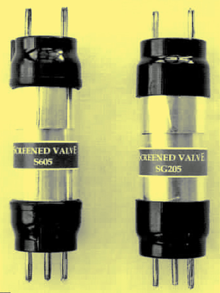
Fig. 12 - Well they work and they don't look too bad. So that's not bad, is it?