|
Within the last year or two completely new apparatus for sound recording in talkie pictures has made its appearance. The growing tendency is to record sound directly on to film, and it is with the various systems employing this method that the author deals in this article. The greatest changes have occurred in the design of the recordings camera itself.
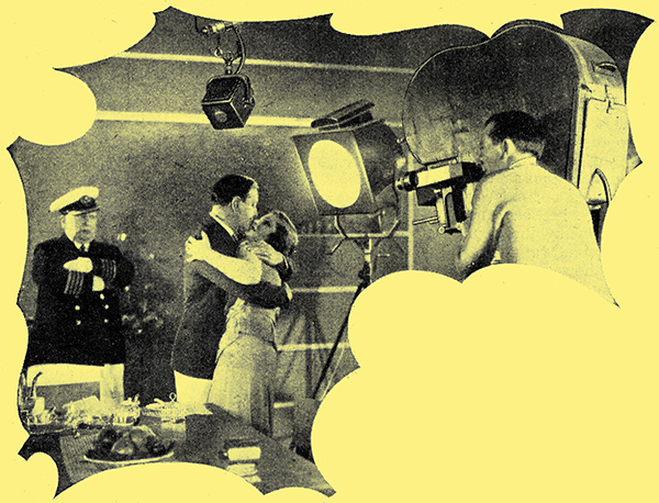
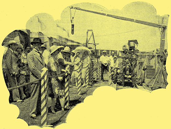
Filming a scene in, the British, Lion Studios, Beaconsfield.
The science of wireless telephony, not content with restricting the number of its progeny to one-to-with broadcasting has given birth to other, and just as precocious, children, one of which is, of course, the talking picture. The talking picture of to-day has rapidly grown from the swaddling-clothes stage, and reached, if. not maturity, at least adolescence. The growth of this youngster has been so rapid and insidious that the general public can hardly be aware of actual progress. made, except by the results which can be observed in the talking-picture theatre. Even so, advances in sound-recording technique fail, by the nature of things, to make their presence felt in the theatre until some considerable time after their inception. In the same way as radio-receiver technique, as applied to the commercial set, is necessarily in advance of that shown in existing receivers, so is recording technique ahead of the results observed in the theatre of the moment.
No apology, therefore, should be needed as a preface to a necessarily brief resume of the latest and most commonly used systems of recording sound for motion pictures. The tendency in commercial practice is to record the sound directly on to film, the exceptions to this rule being disc recording, used in the Warner Bros. Studios, and the iron wire system due to Stille - more commonly known as the Blattnerphone. As the title of this article indicates, the only systems under consideration are those in which the recording medium is photographic film. The choice of such a subject must necessarily presuppose in the reader a knowledge of the fundamentals of photography or, at least, of elementary optics. As such a knowledge is generally possessed by every keen owner of a camera (and who is not such a one in these days?), it is felt that the following short descriptions will be readily followed by anyone.
In all recording systems, one part at least of the process is the same in each case, i.e., the means by which the sound waves are picked up and converted into electrical vibrations. The microphones and amplifying chains are, in principle, the same whatever the system, differing only in relatively unimportant details. The methods of converting the electrical vibrations into a visual record are several, and differ widely in principle.
It is the ultimate aim, when recording sound on to film, to reproduce that sound through the customary channel of photo-electric cell, amplifiers, and loud speakers. Thus, if an image of varying characteristic corresponding to the sound be produced on the film in such a way that when the film is drawn past a light sensitive cell, the light falling on the cell varies with the variations in characteristic, thus modulating the output of the cell, it can be said that the sound has been recorded on the film, irrespective of the manner in which the variations in characteristic have been obtained. The physical property of suitably exposed photographic film to transmit light in varying amounts is made use of in such a manner that the area of film passing the light beam has constantly varying translucent properties. It will thus be realised that a variation in the incident light on the cell may be produced either by constantly changing the density of the photographic image or by varying the amount of opaque image in the area covered by the light. The result in either case will be the same, i.e., the amount of light falling on the cell will vary by the same amounts. There are thus two distinct methods of photographic sound recording - 'variable density' and 'variable area', it is commonly supposed by those whose knowledge of the subject does not extend farther than appreciation of the difference between the two methods, that the process of producing the two types of sound track is confined to different variations of two systems. Such is not the case, however. It is true that there is only one fundamental method of recording a variable area sound track, but there are actually two different methods of making one of the variable density type. The two types of track are shown in the photograph below. It will be seen that the 'variable area' consists of a track of uniform density, but the area of which is constantly varying. The 'variable density' track consists of a band of constant width, but of uneven density. The first type is invariably made by an oscillating light beam reflected from an oscillograph. The film moves lineally, while the light beam has a lateral movement.

The two different types of sound track. On the left is a section of 'variable area' track; the other is 'variable density'.
Two Variable Density Systems
With the variable density system there are, as stated, two methods. One, adopted in Western Electric recording, makes use of a light of constant intensity passing through a slit of varying width. The other method, used by Fox Movietone, produces a track by means of a continually varying light, and a slit of constant width. The difference will become clearer after a more detailed explanation of the systems.
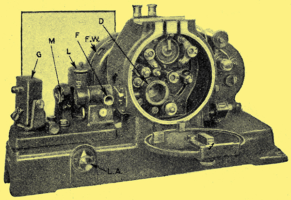
The RCA Photophone Recorder. G, galvanometer; D, recording drum; F, focusing tube; M, reflecting mirror for observing modulation level; L, lamp; FW, fly wheel.
Dealing first with variable area recording, one system has already been dealt with in some detail in these pages. [1] Talking Films: The RCA Photophone System, by W H O Sweeny, The Wireless World, January 28, 1931. Since that article on the RCA Photophone was published, however, the march of progress has produced a completely new apparatus, the chief difference being in the recording camera itself. It may, therefore, be permitted to run over a few of the salient points. An illustration of the RCA PR4 Recorder can be seen above. This, it will be observed, consists of a light-tight chamber, through which positive cinematograph film (i.e., slow, contrasty stock) is drawn at a constant speed of 90 ft/min. The film is passed round a drum D, after being withdrawn from the magazine by a sprocket wheel. After leaving the drum, it is drawn into the take-up magazine by the other side of the same sprocket. In nearly all recording systems, where sprocket teeth are used to move the film through the sound camera, it is essential to filter out the sprocket ripple. Were this not done, the higher frequencies would suffer from a defect known as flutter, i.e., they become modulated by the frequency imparted by the teeth of the sprocket wheel. Also, the linear speed of the film past the light beam must be constant, or variations in frequency will be produced resulting in wows, or momentary alterations in pitch.
Overcoming Wow and Flutter
This linear speed is liable to variations if the film is stretched or contracted at any point in its length. Different systems use different methods of overcoming these difficulties. The RCA recorder avoids both troubles by the use of a magnetic clutch, which enables two loops to be maintained in the film, one on each side of the recording drum, thus isolating the portion wrapped round the drum from the part being moved by the sprocket mechanism. The actual portion of the film being moved past the light is driven entirely by the drum, which is allowed to run perfectly free. The drum is attached to one end of a shaft, on the other end of which is affixed a flywheel. The flywheel has a copper flange attached to it, and runs concentrically with a circular electro-magnet on the sprocket shaft. The electro-magnet induces eddy currents in the copper flange, resulting in the rotation of the drum fly-wheel. The strength of the field of the electro-magnet can be varied, which gives a measure of control of the relative speeds of the magnet and flywheel, In practice, the drum rotates at a slightly slower speed than that of the magnet, thus tending to eliminate oscillations in the speed of the drum and any inclination towards 'hunting'. The motive power applied by the magnet to the drum leaves the film so little to do in this direction that the previously mentioned loops are formed on either side of the drum.
The Optical System

Fig. 1. - Above (A) is a diagrammatic view of the British Acoustic optical system. The lower diagram shows the RCA system.
Turning to the optical system, it may be remarked that the essentials of the latest arrangement are the same as those described before. The chief difference is one of convenience in adjustment. The system consists essentially of a light source, provided by a spiral filament lamp, focused through a condenser lens and light stop on to the mirror of an oscillograph. From here the light is reflected through a cylindrical lens (which distorts the image in a horizontal direction), passed through a horizontal slit, 3 [★] A mil is a measurement that equals one-thousandth of an inch, or 0.001 inch. One mil also equals 0.0254 mm solid star in width, and finally focused through a 4 to 1 reduction microscope objective lens on to the film. The light beam on the film under conditions of no modulation measures 35 mils long by 0.75 mils wide, and at 100% modulation the length of the image varies from zero to 70 mils. The optical system is shown diagrammatically in Fig. 1b. In order to achieve observation of modulation level, half the light beam is intercepted by a mirror, and reflected on to a calibrated screen. The location of the sound track relative to the edge of. the film, which in variable-area recording most important, is controlled by moving bodily the complete optical system. The location control on the RCA recorder is calibrated in mils. The correct distance of the inner edge of the track to the nearest edge of the film is 278 mils. Focusing of the slit image is simplified by observation of the image itself through a special focusing tube which can be pushed into the light beam in the barrel when required. A device is fitted in the recorder by means of which the edge of the film may be marked for synchronising. The component parts of the oscillograph vibrator are shown in Fig. 2.

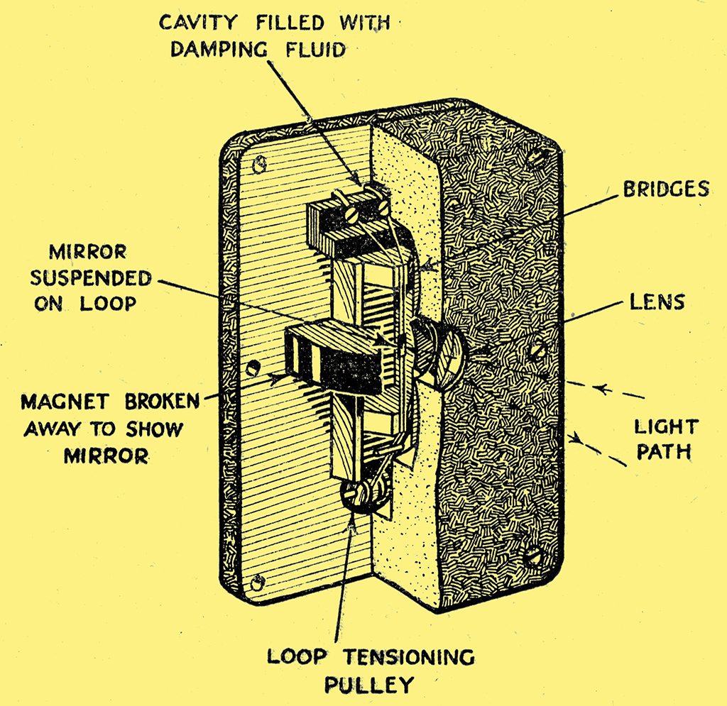
Fig. 2.- The oscillograph vibrator used in the RCA recording system. A small mirror, surrounded by a damping fluid, oscillates in sympathy with speech currents in a loop of duralumin wire. reflecting a light beam on to the film.
This consists of a strip of duralumin wire, mounted in the form of a loop, and stretched tightly over two insulating bridges spaced 11.12 mm (7/16 in) apart. This loop, composed of a strip ½ mil thick and 5 mils wide, has its two limbs separated by a distance of 10 mils. Half-way between the bridges a small mirror is cemented to the two limbs of the loop. The whole structure is then placed in the field of a powerful magnet, and surrounded by a damping fluid. When speech currents are applied to the loop the portion between the bridges vibrates, giving the mirror a twisting oscillatory motion. The natural frequency of the system is located about 6 kHz, and, by means of the damping fluid is restricted to about 5 or 6 dB. For 100% modulation an input power of about 200 mW is required. The exposure lamp shining on to the mirror consumes 6 A at 5 Volts.
Another variable-area system is the British Acoustic system, the initial patents of which date back to 1907, and which has been developed by Dr Kolb. This system is in use at the Gaumont Studios at Shepherd's Bush, and the recorder is illustrated below.
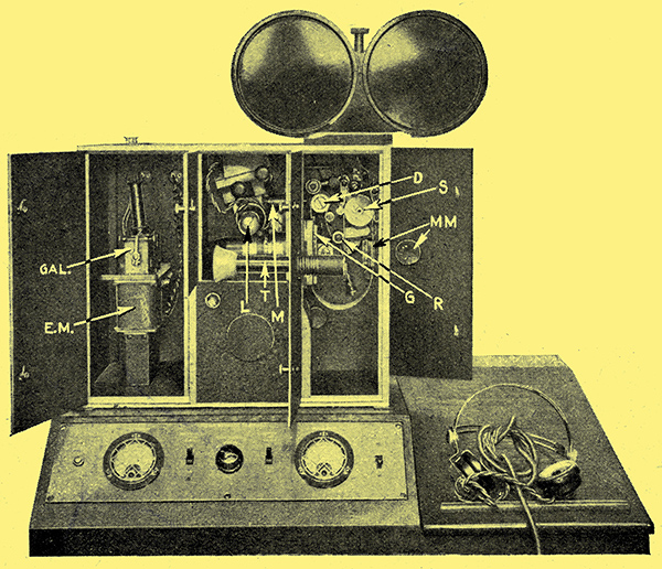
The British Acoustic Recorder. L, lamp; M, marker (synchronising); D, drum; G, gate; S, sprocket; T, telescope; MM, mechanical marker; GAL, galvanometer; EM., galvanometer electro-magnet; R, tensioning roller.
The essentials can be picked out immediately, as they are similar in principle to the RCA recorder. The lamp (L) has a linear filament, differing from the previous type, which was spiral. The image of this filament is focused through a condenser lens on to the mirror of the oscillograph. This mirror, measuring 23.7 mils by 31.5 mils, is mounted horizontally, as opposed to the RCA mirror, which is vertical. From the mirror, the filament image is reflected through a cylindrical lens on to the film. Note that in this system a slit is not used, but that the actual image of the filament is focused on to the film. The sharp focusing of the filament image on the mirror is important, and is facilitated by viewing the image on a screen from the front. It will be obvious that, as the mirror vibrates, so will the filament image move laterally on the film. The width of the light image on the film is 0.015 mm., or about 0.59 mils. A diagram of the optical system is given in Fig. 1(a) A point of interest is that it is claimed that it is impossible for the track location to alter, and the film, owing to the gate, cannot weave, i.e., deviate from a strictly linear path. Modulation can be observed direct on the film, looking at it from the, reverse side. Situated just behind the film, and opposite the light beam, is a prism, which deflects the image of the light through a telescope (T). Half the light beam is intercepted and deflected on to a screen on the recordist's desk. The recordist also has, for the purpose of observing modulation level, a power level indicator. The vibrator is damped, a feature of the damping fluid being that its viscosity is constant between freezing point and 40-45 °C. This means that the characteristic of the vibrator remains constant, whatever the temperature. The vibrator, when damped, peaks about 3 dB at 6 kHz, and has a straight-line characteristic from 50 Hz up to this peak. It requires an input of approximately 150 milliwatts to obtain 100% modulation, although the output stage of the recorder amplifier is capable of 1 Watt undistorted output. The field for the galvanometer is supplied by an electro-magnet taking 2 to 3 A at 6 Volts. This value, however, is not at all critical. The exposure lamp takes 4 A at 5 Volts. With regard to the vibrator, the ribbon is composed of either phosphor bronze or nickel bronze, as opposed to the more customary duralumin of other systems. It is possible that the choice of damping fluid led to the selection of this particular metal.
The Film Mechanism
In recording, the film is drawn from the magazine by a sprocket wheel (S), and then passed round a tensioning roller (R). From thence it is passed round a rough drum (D), being kept tight against this drum by a rubber roller. From the drum the film travels through a gate (G), forms a wide loop, and is returned to the take-up magazine by the sprocket wheel (S). Attached to the drum shaft is a heavy flywheel which is rotated by the friction of the film on the drum. Once it is up to speed, very little driving force is needed to keep it rotating, and its own inertia is responsible for keeping the film running smoothly through the gate. The fly-wheel drum on the one side of the gate and the large loop on the other ensure complete filtration of sprocket flutter. The synchronising marker may be seen at (M). An ingenious device is the mechanical marker (MU), used for punching the bscene' and 'take' numbers on the film without opening the door. Sometimes a device is fitted for imprinting the numbers photographically.
Other variable-area systems are Capt. Round's 'Visatone', used at the Stoll Studios, and at Shepparton; 'Fidelitone', used by Fidelity Films at Worton Hall and 'Ambiphone', a system used at the British International Studios, Elstree. Considerations of space preclude treatment of these methods, though it may be said that they are similar in principle to the systems which have already been outlined.
Outdoor work with microphone and camera. By courtesy of Film Weekly.
Variable Density
Two distinct methods are employed to record sound by the variable density of the film. In one system a constant light source requires the use of a variable slit to control the amount of illumination reaching the photo-electric cell; in another system, the slit is of constant width, fluctuating light: being obtained by a gaseous discharge tube.
Turning now to variable density recording, the system evolved by Western Electric may be found in use at the B and D studios Elstree. This method uses constant light and a variable slit. A photograph of the recorder is below.
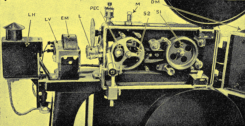
The Western Electric recorder, as used at the British and Dominions studio at Elstree. SIi - main sprocket; S2 - recording sprocket; PEC - photo-electric cell; M - marker; L - lens system; EM - electro-magnet; LV - light valve; LH - light housing; DM - driving motor.
The film is drawn from the top magazine by the sprocket S1, and passed round the recording sprocket S2. This sprocket, which engages only twenty perforations of the film, is driven through a mechanical filter composed of a three-point star-shaped driving member acting through compression springs. This filter ensures that the sprocket shall have a uniform angular velocity, which would result in the linear motion of the film past the light being kept constant. The flywheel forming part of the filter is so balanced that the angular velocity is kept constant to one part in a thousand. After leaving the recording socket, the film is drawn into the lower take-up magazine by the sprocket S1.
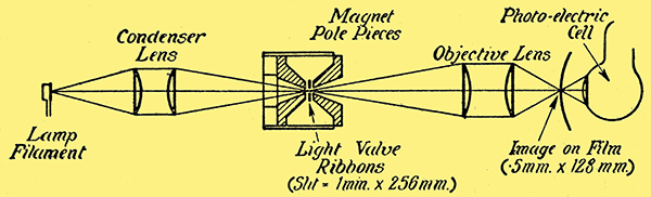
Fig. 3. - The optical system in the Western Electric method of variable density recording.
The light system is seen to consist of a light source; a condenser, a light valve, and an optical system for focusing the image of the valve on to the film. The system is represented diagramatically in Fig. 3, and the light valve is shown in more detail in Fig. 4.
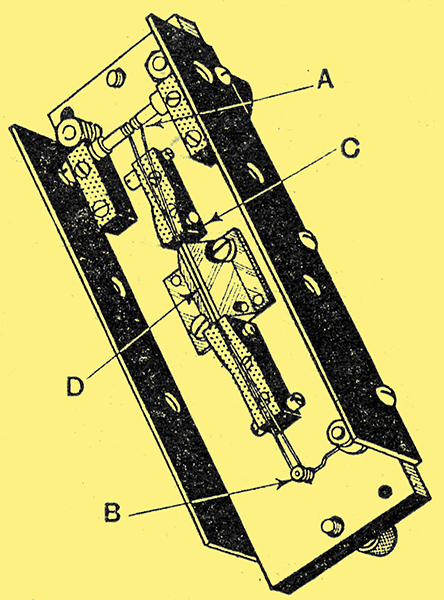
Fig. 4. - The Western Electric light valve. A - windlasses for adjusting tension; B - tension pulley; C - positioning clamps for spacing ribbons; D; - portion of armature, containing slot, through which light enters to the ribbons.
Like the RCA vibrator, it consists of a duralurnin tape, looped and suspended in a plane at right angles to a magnetic field. This tape, which is 6 mils in width and 0.5 mil thick, is stretched over two insulated bridges, the distance between the two limbs being 1 mil. They lie just over the top edge of a slab of metal which forms part of the armature of an electro-magnet, and are separated from it by 3[kmils. In the edge of this metal slab is a slot, measuring 8 mils wide by 256 mils long. This slot tapers out to the back of the slab, Where it measures 204 mils by 256 mils. With the whole assembly complete, the valve is seen to consist of a slit, 1 mil by 256 mils, its sides lying in a plane at right angles. to the lines of force, and centred over the air gap in the electro-magnet, When speech currents are applied to the loop, and the electro-magnet energised, the limbs open and close in sympathy with the current alternations. The natural frequency of the system is about 8,5 kHz. From Fig. 3 it will be seen that the light from the lamp (an 18 Amp projection lamp) is focused on to the plane of the valve. The valve in operation is opening and closing in sympathy with the signal currents. The image of the varying opening is focused, with a 2:1 reduction, on to the film. The length of the image on the film is 128 mils, and, under a condition of no modulation, is ½ mil wide. At 100% modulation the image varies from zero to 1 mil in width. The amount of light reaching the film is constantly varying, resulting in a track similar to that in the right-hand strip in Fig. 1. The power necessary to produce 100% modulation is of the order of 100 milliwatts. Inside the sprocket S2 is a photo-electric cell, and, as will be seen from Fig. 3, a portion of the light falling on the film - 4% - is transmitted through, and falls on the cell. The consequent variations in output of the cell are amplified, and when reproduced by means of a loud speaker are used as a check on what is actually getting on the film. In Western Electric recording the sound-picture cameras are all controlled by the 'Interlock', system. Selsen Motors, controlled by a master motor, are used for driving the individual units. In this way synchronism between the various machines is certain. Practically all other recording systems use synchronous 3-phase motors, Whose speed depends on the frequency of the supply. Using these motors, the only factor likely to produce errors in synchronising will be voltage drop on the line, resulting in 'hunting'.
Varying Light Source Method
The other variable-density system is that used by Fox Movietone. Here, as has been stated, a slit of constant width is employed, while the light varies in intensity. Thus, as the film moves past the beam, the varying intensity of the incident light produces a track of varying density. The light-emitting device is known as the Aeolight, and is a gaseous discharge tube, which varies the amount of emitted light in sympathy with the speech currents applied to it. The tube has two elements - a nickel anode, and a looped cathode, coated with barium and strontium. When the Aeolight is filled with an inert gas such as helium, and a sufficient voltage applied to its terminals, it glows, and the amount of light emitted is proportional to the polarising voltage, In recording, a DC voltage is applied to the tube, which causes enough light to be emitted to give a certain exposure of the track, corresponding to a condition of no modulation. When speech currents are applied, the light emission of the Aeolight varies on either side of the steady condition, which results in the track receiving exposures above and below the no modulation figure. Contrary to the practice in other systems, an optical system is not used for the purpose of focusing the light on to the film. Instead, a quartz slit is used in contact with the emulsion, and the light shines through this on to the film. The slit is composed of a slab of quartz, 0.2 in. square by 20 mils thick, coated with silver. Engraved right through the silver is a line 0.8 mil thick, which is covered by a second piece of quartz, 1 mil thick at the part opposite the slit. The slit is positioned with respect to the film by mounting it in a special floating metal shoe, which has the same radius as the recording sprocket. This shoe is mounted on the Aeolight holder in such a way that, when the assembly is complete, the light shines through the slit and its quartz protection on to the film at the correct point. The sound camera itself utilises one sprocket only, which draws the film through the camera. This sprocket is driven through the customary mechanical filter. The recorder is driven by a motor interlocked with the rest of the system, similar to the method adopted by Western Electric.
The difference between Aeofight and light-valve recorded tracks is a purely photographic one, depending entirely on the portion used of the Hurter and Driffield curve, and a discussion of that difference would hardly come within the scope of The Wireless World
The question of 'ground noise' has not, so far, been mentioned. Ground noise may be defined as the unwanted, and often unavoidable, background which is the almost inevitable result of as comparatively long amplifying sequence, followed by a recording direct on to film. This background, accompanying the reproduction of the recorded sound, may be due to one or more of several causes. Set noise, valve noise, AC pick-up, or dirt on the track all contribute their quota to the ground noise. It is the obvious aim of the recording engineer to eliminate it as much as possible, for it follows that the higher the ground-noise level the more restricted will be the available range between the loudest sound it is possible to record and the least.
Reducing Ground Noise
The loudest depends on the width of the film which is available for use as a sound track. The least is governed by the amount of ground noise present. If the ground noise can be reduced to a figure equal to or less than that of the theatre in which the sound is being reproduced, the reduction may be regarded as satisfactory.
Valve noise, set noise, and system noise, due to pick-up, can be practically eliminated by careful design and maintenance. Ground noise due to dirt is not easy to eliminate, as, however careful the technicians may be in handling the film, a small proportion of dirt is inevitable. It will be obvious that the greater the proportion of light area of track the greater will be the effect of dirt. Dirt, being opaque, will show up against a clear transparency. This fact has led to the invention of a piece of apparatus known as the ground-noise reduction amplifier and shutter. Developed in the RKO studios in Hollywood, and handled by RCA Photophone, it is only applicable to variable-area recording. In a variable-area track it will be obvious that the useful part is the serrated edge. The remainder is serving no useful purpose, as it is the rate of change of area which counts, not the quantity of exposed track. In the illustration, Fig. 1a, the track. shown is the original negative. This is printed to form a positive when it is combined with the picture. Thus where the image is now black it will be white in practice. Thus the greater the area of black in the negative the greater will be the area of white in the positive. This would obviously be unsatisfactory from the point of view of ground noise.
The object of the ground-noise reduction apparatus, or squeeze-track, as it is known in the industry, is to reduce the proportion of clear track. This is achieved by inserting a light moving vane or shutter between the moving-light beam and the track. This shutter is operated by the amplified and suitably treated signal currents, and moves approximately in accordance with them. It is positioned so that it masks the light at the base of the track, and follows the general shape of the envelope. When correctly adjusted it just clears the peaks, so that the outline of the wave-form is allowed to reach the film, and nothing else. Owing to the inertia of the vane it obviously cannot vibrate at the speech frequencies, but moves in accordance with the modulation level. An examination of the left-hand track in Fig. 1 will show that the base line of the track is not a straight line, spaced from the edge of the film a distance of 278 mils, as would be the case of a standard track, but assumes an undulating form, so gradual that the resultant frequency is considerably below the level of audibility. This undulating line moves away from the edge of the film at high modulation levels, and nearer to it at low levels. Thus, in the positive, at low levels, a very small area of clear track is found, which reduces the ground noise and permits the range of recorded sound to be increased considerably at the lower extremity. Using this apparatus, and with ordinarily careful working, a range of about 50 dB should be possible.

The British Acoustic combined film and recording camera for news-reel work. Note the portable amplifier, battery box and connecting cable. The sound is recorded on the same strip of film as the picture.
|