|

With the onset of spring, or of summer, most of us turn to the wide open spaces as a welcome relief from the cooped-up confines of the shack in which we have laboured, listened, or operated over the period of dark winter nights and cold wet days. Most of us set out with high hopes that the sunshine will last out for the day and that we shall have an enjoyable trip - whether it be by foot, train or car. These are, of course, admirable sentiments and, in themselves, constitute part and parcel of the seasonal merry-go-round in which most radio enthusiasts take a part. The great outdoors, however, can be a lonely place for the radio hobbyist - particularly when the absence of a radio receiver causes one to miss that favourite programme - or the result of the latest Test match! To fill this void one must turn to the obvious - a portable receiver.
A portable receiver is regarded by many as a seasonal acquisition, and although true that it is at the present time of the year that the need of one is, perhaps, greatest, it is none the less a fact that such a receiver is a great boon throughout the seasons. It may be used not only out-of-doors but also in every room of the house - well, almost!
A well-designed portable receiver must not only be portable, as its name implies, but it must also be comparatively light in weight, of high sensitivity, reasonably small current consumption, good selectivity and, last but not least, attractive to the eye - the last-mentioned attribute being of paramount importance to the female side of the family.
With the above in mind, no apologies are offered for once again presenting in this volume of the magazine a portable receiver of thoroughly proven worth, which is available not only in kit form, but which is also obtainable at a very reasonable cost indeed. The 'Rambler' was designed and has been marketed specifically for the home constructor. It is supplied to the trade as a kit and is thus available from many of the regular advertisers in this magazine (as here). Purchase of the complete kit of parts, therefore, does not entail any difficulty on the part of the intending constructor from this angle.
The Rambler Circuit

The Complete Circuit.
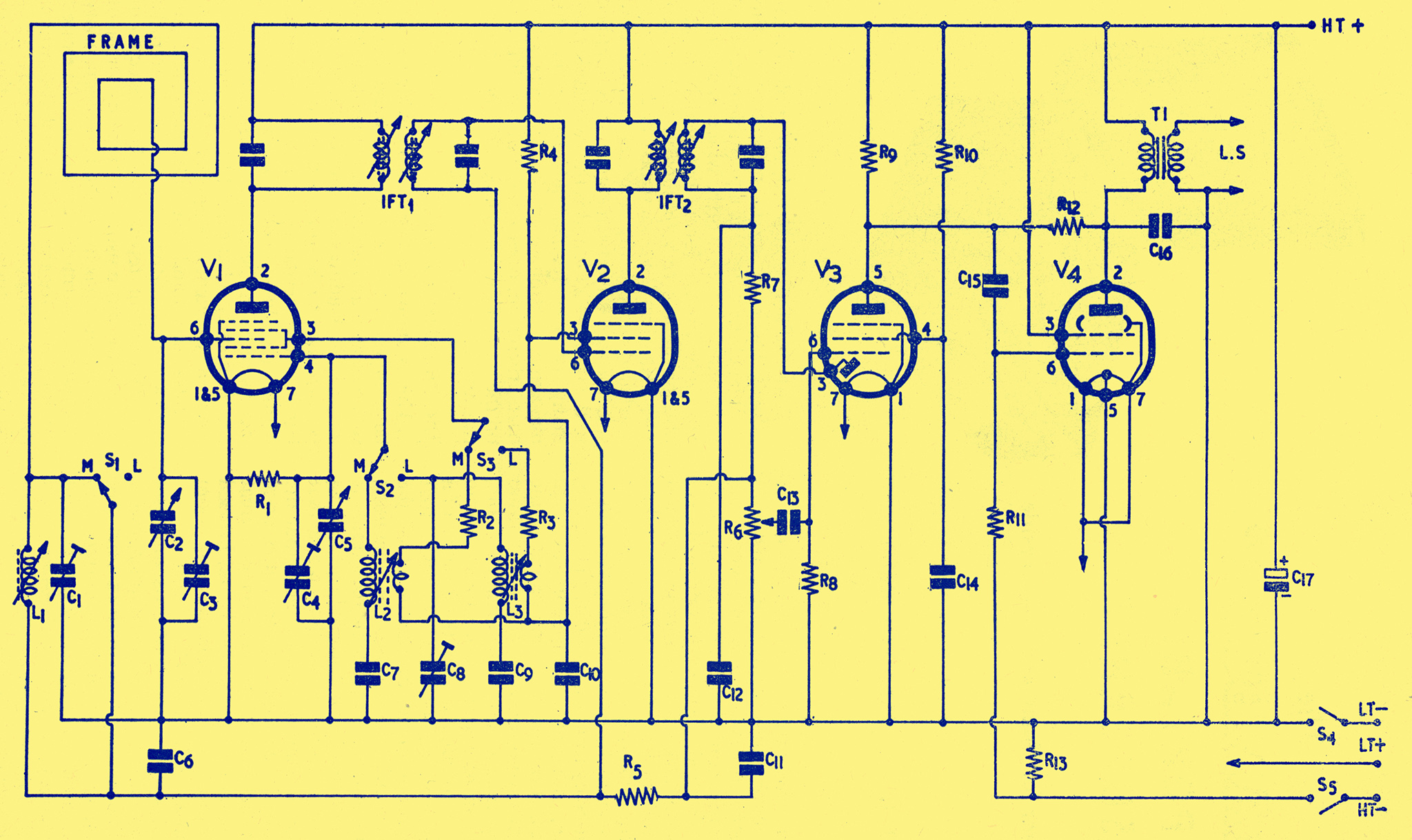
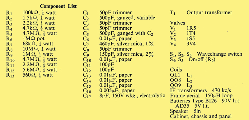
This is shown in Fig. 1 from which it will be seen that it is a two waveband battery superhet with an internal frame aerial feeding into a LW loading coil, thus enabling a high performance to be obtained on both wave- bands. The aerial, of course, is contained within the lift-up lid. Four valves are incorporated in the circuit: these are 1R5 as the frequency changer; 1T4 as the intermediate frequency amplifier; 1S5 as the detector, AVC and first audio amplifier; and a 3V4 high sensitivity output beam tetrode. The 3V4 output tetrode has been selected in place of the more usual 3S4 type by virtue of the fact that it has increased power sensitivity and reduced harmonic distortion. The rated output power for the 3V4 is some 0.27 Watts, this being adequate for most needs associated with a portable receiver of this type. Distortion has been very greatly reduced by the introduction of negative feedback into the circuit.
Automatic volume control (AVC) is applied both to the 1R5 frequency changer and also to the 1T4 IF amplifier. The IF transformers, aerial and oscillator coils are all dust-cored tuned for maximum sensitivity. The IF transformers are all pre-aligned to 470 kHz in order to simplify the lining-up process once the receiver has been completed. The lining-up details, both with and without a signal generator, are discussed later.
The output from the 3V4 tetrode is fed, via a suitable transformer, into a 5-in permanent magnet loudspeaker, this producing excellent tone and volume for a receiver of this type. Bias for the output stage is obtained via R13. The negative feedback component is R12. The numbers shown around each individual valve represent the actual pin numbers of the valve holders themselves.
Little else need be said about the circuit, it being perfectly straightforward, easy to follow and simple to construct. The receiver covers both the Medium and Long wave bands - 190 to 560 metres and 800 to 2,000 metres. The dial is engraved in both red (MW) and green (LW) and this, mounted on to the cream plastic top panel, imparts a very attractive appearance to the set. The cream and grey attache-case type cabinet, complete with cream plastic 'spring-back' handle, measures only 9 in × 7 in × 5¾} in. The weight of the receiver and cabinet, less batteries, is 4¾} lb; complete with batteries it only weighs some 6¼} lb. The cabinet is suitably protected by rubber feet both in the playing and the carrying position.
Assembly

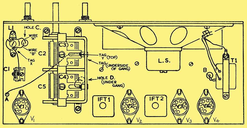
Above chassis layout of components.
Dealing with the assembly of the receiver, all the main components, except the panel and speaker, are fitted to the chassis in the first instance. The panel and speaker are left until construction has otherwise been completed. To commence the assembly, therefore, fit the four valve holders as shown in Fig. 2, using 6 BA × ¾ in screws. Note that the valve holders are fitted from the top side of the chassis and that 6BA solder tags should be fitted with each valveholder as shown in Fig. 3. Having completed this, next mount the IF transformers, ensuring that these are located correctly with regard to pin numbers as shown in Fig. 3. Use 6BA ¼ in screws to hold these IF transformers in position. Fix into position T1, the output transformer, on to the chassis deck in the same position as that shown in Fig. 2. Note that two solder tags are required to be fitted with T1, one tag below and one above the chassis (see Figs. 2 and 3). Secure the 6-way tag strip under the chassis as shown (Fig. 3).
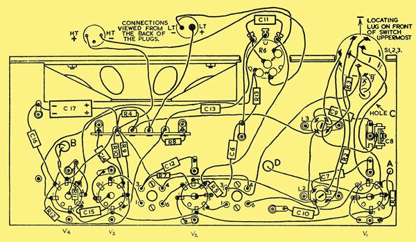
Underside of chassis layout and wiring.
Mount C8 under the chassis and C1 above the chassis, both being held by the same 6 BA × Frac14; in bolt, with a solder tag on the underside as shown in Fig. 3. Next fix both coils L3 (Q09) and L2 (Q08) under the chassis by means of 8BA × ¼ in screws. Note the position of the slot in the tag rings from Fig. 3.
Having completed the above, it will now be necessary to fit the two-gang tuning capacitor C2, C5, but before doing so it would be advisable to solder the two leads which go to the underside of the capacitors into position, as this may be rather difficult once the component has been fitted into place (see Fig. 2). Fit the ganged capacitor using 6 BA × ¼ in screws, using washers under the heads and a solder tag under the nut of the rear fixing bolt (see Fig. 3).
Next, fit R6, the volume control, and the wave-change switch (S1, S2 and S3) to the chassis; but do not tighten the nuts because the panel will have to be fitted under them at a later stage. Finally, mount L1 (QLl), the loading coil, in the position shown above the chassis. This coil stands away from the chassis and is mounted on 8 BA × ½ in screws. Reference to Fig. 3 will make this clear. It has been found necessary to space this coil from the chassis deck because the 'Q' of the coil would have been lowered had this been fixed in the more usual manner and this, in turn, would have resulted in an inferior performance to that obtainable when mounted as shown. With coils L2 and L3, this method of mounting is, of course, not necessary as these two coils are not themselves in the signal circuit.
With the assembly now completed except for the panel and speaker, the wiring-up process may be commenced. It is best to do this by commencing with the earthed connections; these are clearly shown, as are all other connections, in Figs. 2 and 3. It is a good plan to deal with these connections logically, commencing with the earthed wiring points of V1 and continuing to V4; and from there to other similar points of the circuit. The earthed solder tags are clearly shown and no difficulty should be experienced - even by the beginner - with regard to these solder connections. Note that the centre spigots of each valveholder are contained within the earthed wiring plan. Having completed all of these points except, of course, that of the speaker which has not yet been mounted, proceed next with the valve heater chain. These connections are from the LT+ pin of the battery plug (largest one), to the tag strip and from there to pins 1 and 7 of V4, from there continuing to pin 7 of each valve in turn and ending at V1.
The fitting of the resistors and capacitors may be in any order, the layout of these components not being unduly critical. In order to avoid confusion, however, it would be best for beginners to solder into position those components contained around each valve-holder, commencing with V1, and marking, out with ink on Fig. 3 each item as it is soldered into position. In this way, the wiring-up process is considerably simplified for the novice.
Note the leads that go through the chassis. via hole C; these have been marked 'A' and 'B' in order to avoid confusion (see Figs. 2 and 3). The leads from the tuning capacitor, previously soldered into position before mounting the component, go via holes A and D respectively. The correct polarity of the capacitor C17 should be noted when soldering this into position. The leads that go via hole B are from the underside of T1. Careful attention to Fig. 3 will ensure that no possible mistake is made with respect to the wiring up of the circuit; the drawing is self-explanatory and no further textual guidance is therefore required.
Fitting the Speaker and Panel
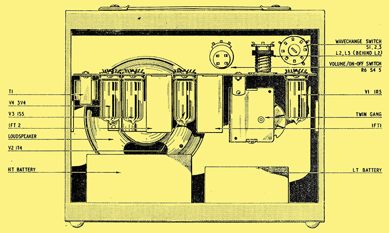
Rear view of the chassis showing position of the main components.
Mount the speaker to the back of the panel, using 6 BA × ½ in screws for the purpose. Ensure when mounting the speaker that the tag connections of this are on the same side of the chassis as T1. Remove the nuts from the volume control and the wave-change switch, fit the panel and refit the nuts, taking; care to tighten these with due regard for the plastic panel. Make sure, at the same time, that the small 6 BA clearance hole towards the opposite bottom edge aligns perfectly with the small hole in the chassis. Next fit a 6 BA ¼ in screw through this hole and lock the nut on the inside, thereby fixing the front panel firmly to the chassis. Having proceeded thus far, fit the plastic cursor and the two knobs to the other controls.
Fitting the Frame Aerial
Remove the inset to the cabinet lid by unscrewing the four corner screws. Fit the frame aerial with about 6 inches of lead left for connecting to tag X and Y indicated in Fig. 2. Four wood screws are provided for holding the completed receiver in the cabinet.
(To be continued)
|