|
Details of a sensitive 7-transistor medium wave superhet portable which may be builtt, at reasonable cost, by the home-constructor.

The complete receiver.
Although the commercial manufacture of transistor receivers in this country appears to be lagging somewhat, the same cannot be said for equipment which is built at home by the amateur. In the home-constructor sphere a number of successful designs have been made by amateurs, and it is interesting to mark the fact that The Radio Constructor has been foremost in presenting designs in this particular field.
The receiver which is described in this article has been developed and is presented by Henry's Radio Ltd. and employs some of the more advanced design features which are feasible with components at present available. It should be noted that all the component parts for the receiver may be obtained through normal channels; and the constructor is not expected to wind his own coils, or anything of that nature. The writer understands that the receiver may be obtained, in kit form, from advertisers in this issue.
The Circuit
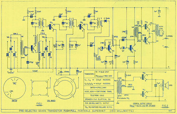
Circuit diagram.
The circuit of the portable transistor receiver is illustrated in Fig. 1. As may be seen, care has been taken to keep the number of components required to a low figure, this simplifying layout problems and reducing cost.
A pre-set tuning arrangement is employed in the frequency-changer stage, this helping to eliminate the difficulties incurred when signal strength has to rely on very accurate tracking. Three pre-tuned stations may be selected, and the use of trimmers ensures that these are received under conditions of optimum sensitivity; The frequency-changer stage is built around TR1, this being an RF junction transistor (blue spot), The ferrite frame tuned coil is connected, via switch SW1, to any of the pre-set capacitors, C1, C2, or C3, as required. A low-impedance secondary coil on the ferrite frame applies the desired signal to chassis and the base of transistor TR1. TR1 also functions as an oscillator, the oscillatory circuit employing a feedback winding instead of relying on conditions of negative resistance in the transistor. This method of operation ensures that reliable oscillations of adequate amplitude are provided. The oscillator coil is tuned by either of the pre-set capacitors C4, C5, or C6; these being selected by SW2. SW1 and SW2 are ganged and, together, form the station selector switch. The ferrite frame and oscillator coil are designed to cover the medium waveband.
By reason of the bias applied to its base via the 8.2 MΩ resistor connected to the HT negative rail, TR1 functions in a non-linear mode. In consequence frequency-changing takes place, and the intermediate frequency of 315 kHz is applied to the first IF transformer. The secondary of this transformer connects to the base of TR2 which operates as an earthed emitter amplifier. TR3, also earthed emitter, follows TR2 in similar manner, the two transistors in cascade forming the IF strip of the receiver. It will be noticed that a separate 1.5 Volt cell, connected in series with the main HT supply, feeds the emitters of TR2 and TR3. The use of a separate cell in this fashion confers several advantages, one of these being that a higher HT potential is available at a point where a high degree of amplification is required. The major advantage, however, is that the use of the cell enables a considerable simplification to be effected in the IF biasing arrangements and eliminates the necessity for an automatic bias resistor. Automatic bias circuits are rather wasteful in receivers of this type. The current drawn from the 1.5 Volt cell is low, and it should need to be replaced only infrequently. The third IF transformer feeds into the crystal diode and thence to the 10 kΩ volume control which forms its load. Audio frequency from the slider of the volume control is next applied to TR4. This transistor, with TR5, makes up a relatively high gain AF amplifier. The HT feed to TR4 is decoupled. TR5 drives the output transistors, phase inversion being provided by the transformer in its collector circuit.
The Output Stage
The output transistors, TR6 and TR7, work in Class B, thus enabling a relatively high power output to be obtained without excessive battery drain. In the circuit shown in Fig. 1, TR6 and TR7 are of the same type as is employed in the IF and AF stages of the receiver, and they provide an output power of approximately 150 mW. The speaker transformer recommended for use with these transistors is the Fortiphone unit type A204. The secondary of this transformer should be connected to a speaker of 3 Ω voice coil impedance. It is worth mentioning that both the transformers just mentioned are miniature types intended especially for transistor circuits.
An alternative output circuit is shown in Fig. 2. This uses two Mullard OC72's and provides an output power of 200 mW. The input circuit to the OC72's is the same as that illustrated for TR6 and TR7 of Fig. 1, but the output circuit differs somewhat insofar that no speaker transformer is required, the two transistors feeding directly into the centre-tapped voice coil of the speaker. The speaker used here is an Elac 7 in by 4 in elliptical model having a 120 Ω centre-tapped voice coil. As will be realised, the direct coupling into the loudspeaker ensures that a very high degree of efficiency is realised.
Constructional Details
Although the receiver contains a relatively large number of amplifying stages, problems of layout are not necessarily as difficult as they would be in a receiver of similar gain employing valves. The main reason for this is that, since transistors are low impedance devices, unwanted capacitive couplings have less effect so far as the transference of energy from one circuit to the next is concerned. From the constructional point of view, all that is needed is a sensible and logical layout which keeps leads carrying RF and AF voltages reasonably short. A minor precaution to observe is that IF transformer and coil cans should be spaced from each other by a distance greater than ¾ in.
The construction of the receiver chassis is liable to incur the use of techniques which differ slightly from those encountered in valve equipment. This is due to the fact that it will be found most convenient to mount the components on a sheet of insulating material such as Paxolin or Perspex rather than on a metal chassis. A single plane chassis is all that is required, and connections to the various components and transistors may be made with the aid of solder tags, these being directly bolted to holes drilled in the chassis. Such holes may be made exactly where required. So long as care is taken to ensure that a low resistance earth path exists for the various stages, this method of construction allows quite an efficient layout to be achieved. When a chassis made of insulating material is used, it is advisable to see that the metalwork of such components as switches and volume controls is connected to the earth line. The same remark also applies, of course, to any screening cans that are used in the circuit.
The two photographs accompanying this article illustrate a prototype receiver fitted into a Perspex cabinet, and provide a typical example of the professional appearance which can be given by the receiver. The cabinet shown is one supplied by Henry's Radio Ltd. as an assembly kit.
In the photograph showing the back of the receiver it will be noted that the frequency-changer stage is at the right-hand side. The six station selector trimmers are readily visible, the selector switch being fitted directly behind these, with its spindle protruding through the top of the cabinet. The layout then proceeds in logical fashion to the left-hand side of the chassis, the volume control being mounted at this point. The knobs of the volume control and station selector switch appear symmetrically on either side of the carrying handle.
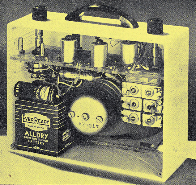
Rear view.
|
