|
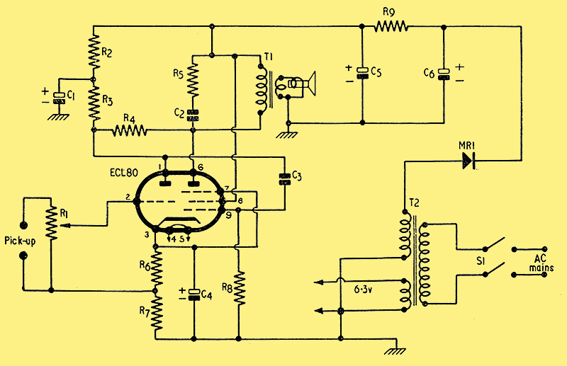
Circuit diagram.
This simple and inexpensive gramophone amplifier, intended for use with a modern electric-motored record player and crystal pick-up with sapphire stylus, has quite a number of unusual and attractive features. Although the chassis is small and compact, every component is readily accessible for wiring, testing and, in the event of breakdown, easy replacement.
The use of a single valve reduces cost to a minimum, but still gives sufficient output for all ordinary domestic purposes, provided that the unit is used with a fairly large and sensitive speaker - say, a 10-in type in a good-sized wooden cabinet.
The valve is an ECL80, which is a combined triode and pentode, thus giving two stages of amplification. Despite its simplicity, the circuit incorporates a form of negative feed-back, giving very pleasing quality - quite comparable with that obtained from some amplifiers of a much more expensive and ambitious type.
Most types of cabinet will readily accommodate the chassis, as it is small, light and radiates very little heat. It can be fixed in position by a single nut that on the one-hole fixing bush of the volume control!
Chassis and Layout
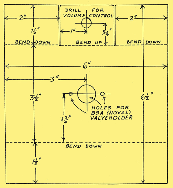
The chassis before bending.
The components are assembled on a simple, inexpensive chassis made to my specification by Denco (Clacton) Ltd., out of 16 SWG aluminium (see Figs. 2 and 3). The two large holes, for valveholder and volume-control bush, can be punched very neatly by the manufacturers of the chassis. But the remaining holes are all small ones which you can very easily drill yourself; they are not shown in the diagrams, as their exact positions can be most accurately marked out by arranging the actual components on the chassis and scribing the fixing-hole centres direct on to the surface of the metal.
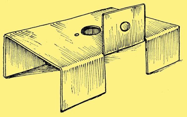
The chassis after bending.
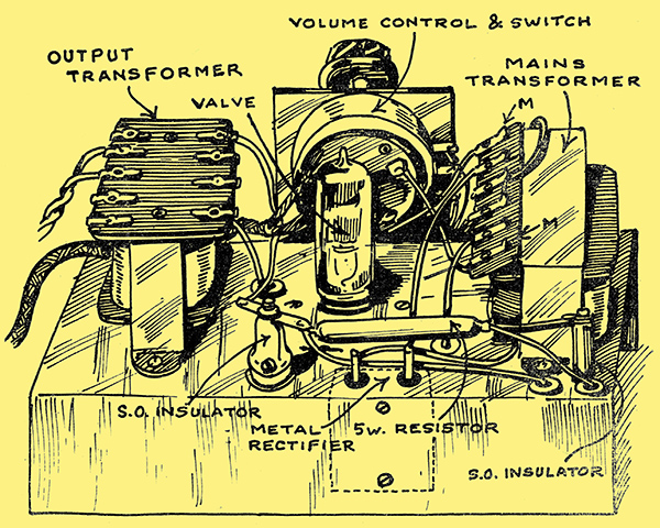
Construction is easy and straightforward. The transformers, volume control, 5 Watt wire-wound resistor (supported on stand-off insulators) and, of course, the valve, are mounted above the deck. The rest of the components are carried on the underside of the chassis. The large 3-in-1 electrolytic capacitor (8 + 32 + 32 μF) is mounted in a clip directly under the mains transformer, while the smaller capacitors and resistors radiate from the valve holder in convenient positions for short wiring and easy access. The metal rectifier is bolted to the vertical rear portion of the chassis, on the inner surface, the connecting tags being led up to the upper side of the 'deck' through large holes drilled to give ample clearance around the tags. Although not shown in the diagrams, suitable fuses should be incorporated in this (as in all other radio apparatus) to protect the valve, metal rectifier, etc. There is room to mount small cartridge-type fuses, in holders, on the chassis between the mains transformer and the valve position. There is also ample space under the chassis, immediately below the output transformer position, for a pair of fuses in the mains leads, on their way to the double-pole switch. Any leads passing through holes in the metal chassis should be well insulated by rubber grommets.
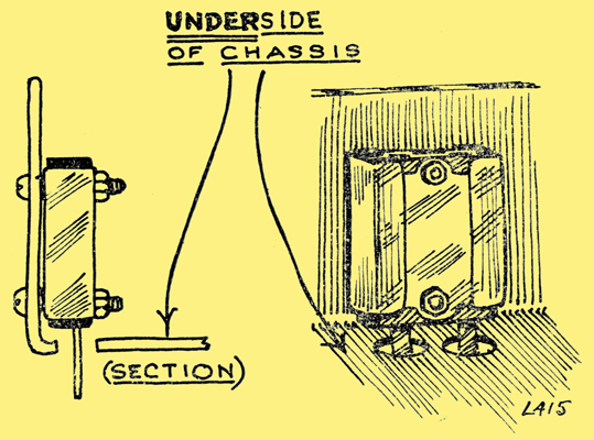
Mounting the rectifier.
The power supply (for AC mains only) incorporates a double-wound transformer and uses a metal rectifier of the new miniature contact-cooled type, which runs beautifully cool if fitted in close contact with the chassis back, as shown above.
Safety Precautions
The completed amplifier from the rear.
As there are 'live' parts both above and below the chassis, the amplifier should nor be used without being totally enclosed in a suitable cabinet of insulating material. If it is necessary to handle the amplifier during preliminary bench tests after construction, due precautions should be taken against risk of shock. The outer pair of tags on the mains transformer are connected to the mains input, and are therefore very much alive! The wisest plan is to cover the whole of this tag panel on the mains transformer with a strip of good quality 1 in wide black insulating tape of the self-adhesive type, to avoid any risk of accidental contact with the live tags.
As the chassis is isolated from the mains by the double-wound transformer, it is not 'live' (as in the case of AC/DC amplifiers) and can, therefore, be properly earthed to the third (earthing) pin of the mains plug.
Screened wire, with the metal screening braid properly earthed to chassis, is used for the signal grid connection on the triode section of the valve. The lead to the signal grid of the pentode section need not be screened if it is kept very, very short - the feed capacitor should be connected right up against the grid pin soldering tag.
Needless to- say, the pick-up leads should also be of screened twin flex-with the screening braid well earthed as a precaution against hum.
Although the two transformers were not mounted at right angles to one another (as they should be in theory!), no trouble was experienced from this source.
An efficient, up-to-date pick-up with sapphire stylus gives quite enough output for adequate volume from this simple amplifier. It won't shake the floor, of course! The ECL80 is rated at only one Watt. But provided the loudspeaker is a good sensitive one, the reproduction is quite loud enough for the average room and the average listener's liking.
The Vintage Audio Workshop produced a video explaining this circuit.
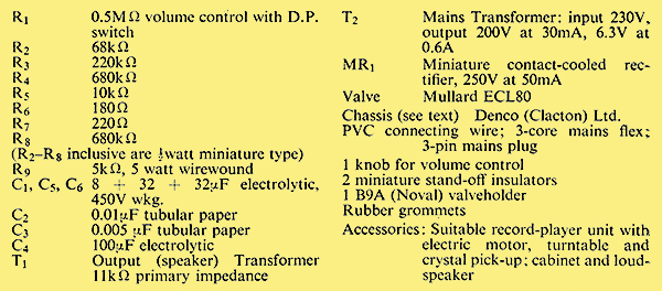
Components list.
Postscript - Building the amplifier.
|