|
Will automatic volume control become popular in this country? Such controls are to be found in a large number of receivers in America, but in spite of obvious advantages there are certain shortcomings which are difficult to obviate. The article affords a valuable topic for discussion and explains the underlying principles of automatic volume control.
Little published data has appeared in this country on the subject of automatic volume control, and at the time of writing it is believed that no British set includes this refinement, Such controls are quite common in America, but their absence in British sets does not indicate any inability on the part of their designers to include them, but rather a doubt as to whether, in actual fact, they are a desirable feature. This is by no means a technical matter; it is more a psychological point upon which both the technical and the non-technical are equally competent to judge. It is in an endeavour to obtain opinions as to the desirability of automatic volume control that this article has been written, for it is obvious that a fair judgment cannot be formed without knowing at least the audible effects of such a control, and preferably also having at least some idea of the methods by which it may be achieved.
The object of an automatic volume control is to adjust the sensitivity of a receiver in such a manner that, whatever the actual strength of the signal tuned in, the audible sound output from the loud speaker remains at a constant value. As the tuning dial of the receiver is rotated, therefore, all stations should come in at the same volume, and it should prove impossible to distinguish distant stations from the local merely by their strength. It must not be assumed, however, that the control smooths out the light and shade, the loud and soft, passages of musical reproduction. It does not, for it is operated by the carrier of the incoming signal, and not by its modulation, upon which the reproduction depends.
It will be obvious that the automatic volume control must be operated by the voltage developed by the carrier of the incoming signal after it has been amplified, and that, furthermore, it must act to reduce the amplification given by the HF stages. It is normally impracticable to make this voltage operate any potentiometer device for the control of volume, and the usual procedure, therefore, is for the rectified carrier voltage to be applied to the grid or screen grids of the HF valves in such a way as lo reduce their mutual conductance.
Separate Valve AVC
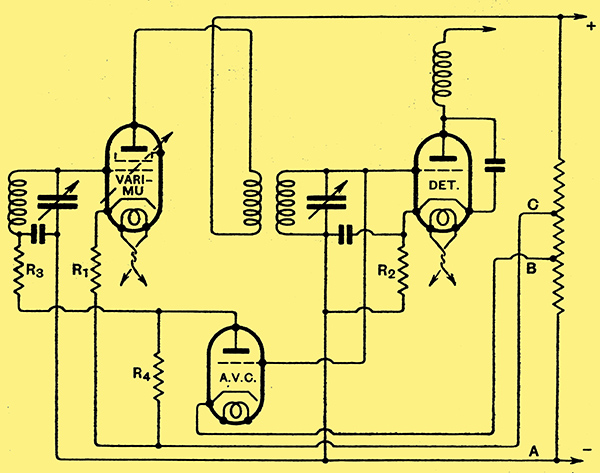
Fig. 1. - A popular American AVC circuit in which an extra valve is used purely for control purposes.
One of the commonest circuits for the attainment of this is shown in Fig. 1; in this particular example a variable-mu stage is transformer-coupled to an anode-bend detector, but this does not directly affect the control, and other methods could be employed. Under conditions of no input signal the HF valve has its minimum negative bias due to the voltage drop along its bias resistance R1, while the detector is also self-biased by the resistance R2. The AVC valve has its grid negatively biased to the point at which the anode current is zero by the voltage developed between the points A-B on the voltage divider across the HT supply. The grid of the HF valve is returned to the voltage source through the decoupling resistance R3 and through the automatic control bias resistance R4. With no signal there is no current flow through R4, and so the bias on. the HF valve is only that due to its own self-bias resistance. When a small signal is applied the conditions are substantially the same, and the control valve has little or no action. The circuit functions as any other, therefore, until the signal voltage applied to the detector is sufficient to actuate the control valve. When this occurs there is rectification in the control valve just as in an ordinary anode-bend detector, and a current flows through R4. This current sets up a voltage across the resistance which is applied through R3 as additional bias to the HF valve, and so reduces its amplification. As the amplification is reduced the voltage applied to the detector and the control valve is also reduced, and a balance point is reached at which the system is stable.
It is obvious that the greater the signal voltage applied to the detector the greater will be the HF valve bias voltage and the lower the amplification. It is obvious, further, that for a strong input signal the detector input must be greater, in order to provide the higher bias voltage, than for a weak signal. It is thus impossible for the control completely to fulfil its function of maintaining the detector input at a constant level. The real action of the control, therefore, is to keep the detector input more nearly constant than it would be in the absence of any such automatic volume control, and this may be achieved to such an extent that variations in volume are aurally negligible.
The merit of this particular method of obtaining control is that a wide range of control is possible, and that it permits the receiver design to be more or less normal. It suffers from several practical disadvantages, however, for it has been found that in certain cases the AVC valve must be a picked specimen, and that there is also a possibility of distortion being introduced. Furthermore, the AVC valve requires a. positive anode potential which must be added to that required by the HF valves, so that the total HT voltage is increased. If all the valves be heated from the same winding on the mains transformer, this AVC anode voltage appears as a potential difference between the heaters and cathodes of the HF valves, Where it might have a detrimental effect upon valve life.
Diode AVC
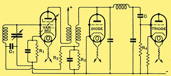
Fig. 2. - A circuit employing a diode for both detection and automatic volume control; an additional valve is usually needed as an amplifier to compensate for the low efficiency of the diode.
Although this circuit is very widely used, therefore, it is open to certain objections which are not present in another type of control which is shown in Fig. 2. This control is considerably simpler than the one just described, and it does not necessarily entail the use of an extra valve. It will be seen that a diode detector is used; and that the automatic bias potentials are obtained directly from this. The HF valve is self-biased in the usual way by the resistance R1, and this bias is applied to its grid through the decoupling resistance R2 and the detector resistance R3, through which there is no current flow in the absence of a signal.
When a signal is applied to the diode there is a direct-current flow through the resistance R3 with the result that the anode is maintained at a potential negative with respect to its cathode. There is no current flow through R2, however, so that the grid of the HF valve is at the same DC potential as the diode anode, and negative with respect to the diode cathode. The diode cathode, however, is negative with respect to the HF cathode on account of the bias resistance of this valve, so that it will be seen that the rectified carrier voltage appearing across R3 is wholly applied to the HF valve as negative grid bias.
The application of the signal to the diode also causes a modulation-frequency current to flow through R3, and hence a modulation- frequency voltage to be set up across it, and this is communicated to the LF valve through the usual coupling capacitor C and grid leak R4.This LF voltage, however, must not be allowed to reach the first valve, so that the decoupling resistance R2 and capacitor C1 are essential features of the circuit.
If the resistance R3, be high compared with the internal resistance of the diode, we may assume roughly that rectification is 100% efficient, so that if we choose a value of 1 MΩ for R3 we shall obtain 1 Volt of bias for every signal volt applied to the diode. The maximum signal input to the diode, therefore, must obviously depend upon the maximum bias voltage required for the HF valves, and if conditions were such that 50 Volts bias were required, then we should have to operate the diode with a signal input of this same figure. In the diode itself this does not necessarily lead to any difficulty, but it may complicate the design of the preceding HF stage.
In practice it would probably be rarely necessary to work with such a high input voltage, and it should be generally satisfactory to legislate for a voltage of about 20 only, at which figure no particular difficulty should be met with. This method of volume control has the advantage that the same valve is used both for volume control and for detection; at first sight, therefore, no additional valve is needed. This is only true, however, when the receiver with which it is being compared is also fitted with a diode detector, for if a comparison be made with an ordinary set fitted with grid or anode-bend detection, then an additional stage of amplification is necessary to make up for the loss due to the use of a diode.
Such additional amplification can take the form of extra HF amplification, but more usually a further stage of LF amplification is employed. On the score of cost, therefore, there is little to choose between the two methods of automatic volume control. The diode, however, has the advantage of being simpler, of giving rise to no abnormal potential difference between heaters and cathodes, of requiring no extra HT supply, and of giving less risk of distortion.
The Wunderlich Valve
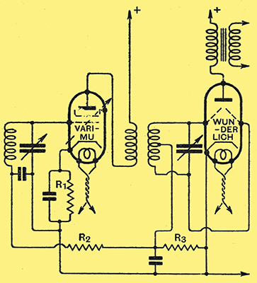
Fig. 3. A circuit employing the new American Wunderlich valve, which acts as a full-wave diode detector, an LF triode amplifier, and a volume control.
Although of little practical interest at the moment in this country, it is important that the newest method of all should not be omitted from this discussion. within the last few months, a new type of value has been developed in America expressly for the purpose of simplifying automatic volume control circuits, and it is an extension of the diode method just described. The circuit is given in Fig. 3, and the special valve, which is known as the Wunderlich, contains, in addition to the usual heater, cathode, and anode, two identical grids. These grids are connected in a push-pull manner to the tuned input circuit, from the centre tap of which a resistance R3, shunted by a capacitor, is connected to the cathode.
Full-wave rectification of the signal is obtained, therefore, and the rectified DC and signal currents flow through R3, across which they set up,potential differences. The DC voltage is applied as automatic bias to the HF valve through the decoupling resistance R2, and the usual minimum bias is obtained through the use of R1. The modulation frequency voltages across R3, however, are applied simultaneously, and in the same phase to both the grids of the detector, which are thus effectively in parallel. These potentials then affect the anode current, and the LF signal appears amplified in the anode circuit in the usual way. The HF input voltages, however, although they are applied to the grids in equal proportions, are applied in exactly opposite phase, so that they do not affect the anode current, and signal frequency HF currents are not found in the anode circuit.
In its action as a volume control valve the Wunderlich valve is the same as that of the diode circuits previously discussed. The novelty lies chiefly in the special type of valve, which is enabled to act both as a diode and as an LF amplifier. The use of automatic volume control with this valve, therefore, does not necessitate the use of an extra stage of amplification.
AVC in Practice
Now that we understand some of the methods by which automatic volume control may be obtained, and we realise that it is a perfectly practical proposition, it is fitting to enquire what effect it will have upon the operation of a set. In the first place, if the desired signal be so weak that the receiver must be working at full sensitivity for its reception, the control will have no effect, and the action of the set will be no different from that of any ordinary type. It is only on the reception of stations for which the volume control of an ordinary set would have to be reduced that the automatic control comes into action.
Over the range of the control, all stations, whatever their actual strength, will deliver the same volume from the loud speaker, provided that they are all modulated to the same extent. The volume 'variation' of fading, therefore, is counteracted, and this is perhaps the most important advantage of automatic volume control, particularly in short-wave receivers. When a station is fading, however, the general mush level caused by atmospherics and extraneous noises does not usually fade as well. The result of a controlled receiver, therefore, on a fading signal is to give the curious effect of a constant signal with a fading background. A signal which is fading, moreover, is usually distorted at times, due to the fading effect being different for the carrier and sidebands; although automatic volume control will hold the volume level constant, it will do nothing to counteract the distortion introduced by fading. It is quite possible, therefore, for the full volume distortion and fading mush level of an automatically controlled set to prove more unpleasant than the normal signal fading of an uncontrolled receiver.
Visual Tuning
Since the automatic control holds the output constant, irrespective of the signal input, within limits, it is almost impossible to tune in a station by ear in the usual manner, for no optimum setting of the tuning dial can be found. It is essential, therefore, for receivers to have some form of visual tuning indicator, which may take the form of a neon tube, or more usually a milliammeter operated either directly or indirectly by the HF valve bias voltage. With such an indicator, of course, no tuning difficulty is met with, and it is in fact easier than the normal tuning by ear. The cost of the indicator, however, must not be overlooked when computing the extra expense of an automatic volume control.
A further point in the operation of a controlled set which may prove disadvantageous is that as the tuning dial is rotated the sensitivity of the set is continually varying in accordance with the variations in the signal inputs. As the set is mis-tuned from a station the sensitivity rises until it is at its maximum when the set is tuned midway between two stations. At this point, therefore, the full output of the set will be obtained on mush, local interference, and frequency modulation interference. Instead of obtaining silent points between stations, therefore, we should normally obtain strong mush points.
Volume Control
Since the automatic volume control is really a control only over the sensitivity of the set, and is intended to keep the detector input constant, it is necessary to fit in addition a normal type hand-operated volume control in the LF circuits, so that the loud speaker volume can be regulated to the desired level. This control, of course, requires only occasional adjustment when at change in the speaker volume is needed, and not for every station tuned in. By reducing the setting of this control when tuning, however, the disadvantage of the automatic control in giving a high mush level between stations can be overcome, so that this effect alone need be no great deterrent to its use.
An effect which is often stressed as a great advantage of automatic control lies in the elimination of the terrific bursts of volume sometimes. found when inadvertently tuning through the local station. This is undoubtedly true, but it is not necessarily a great point in favour of the control, for it may be obtained more simply by other means. If the detector operating conditions be correctly adjusted, for instance, it may be made to overload when the input exceeds a certain value and excessive volume is then avoided without the use of additional apparatus. This course has been adopted in the more sensitive receivers described in The Wireless World, notably in the Monodial AC Super and the Modern Straight Five, and has proved very satisfactory in practice.
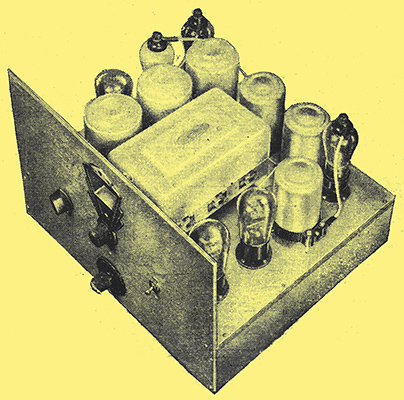
The Wireless World Monodial AC Super a receiver of the type to which automatic volume control could be applied.
It will be seen, therefore, that the advantages of an automatic volume control are the elimination of overloading when tuning through a local, the reception of all stations at approximately the same volume level, and the avoidance of the volume variations of fading. The disadvantages are a high level of background noise between stations, a variable mush level on a fading signal, and the reproduction of fading distortion at full volume, and, of course, the additional apparatus.
It will be obvious that the control is unsuitable for inclusion in the less sensitive types of receiver, and it would only prove useful in superheterodynes and multi HF straight sets. Moreover, the control cannot normally be added to an existing receiver, for the whole apparatus must be designed from the start for working with automatic volume control.
In the Writer's opinion, the advantages and disadvantages of automatic volume control are rather evenly balanced, with the result that it is difficult to form an opinion as to whether its use is justified in high quality receivers. This article has been written, therefore, not with the idea of either advocating or condemning the system, but rather with the hope of stimulating interest in the subject. Opinions will naturally differ as to the relative values to be assigned to the merits and demerits, and it is hoped that as a result of this article some conclusion may be reached as to the way in which automatic volume control would be regarded. Should there be a definite consensus of opinion in its favour, then it will undoubtedly be included in some future receiver design.
|