|
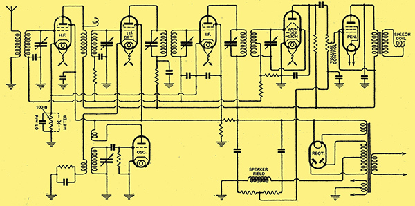
Fig. 1. - Circuit diagram of a complete six-valve superheterodyne embodying the Wunderlich valve and an AGC system.
Previously [★] We do not have this issue yet the principles underlying the various systems of automatic volume control were explained, and reference was made to the Wunderlich valve, Fig. 1 shows a 6-valve superheterodyne circuit employing this valve and the AGC system. Although the valve is not available in England, unless imported from America, there are certain advantages in including the full circuit in this article. In the first place it enables the reader to obtain a more comprehensive idea of the application of the principles which have just been discussed, Secondly, an examination of the circuit will reveal the circuit simplification which is possible with the new valve. Thirdly, there is obvious scope for experimenters to secure similar results by using two carefully matched triodes connected in push-pull to replace the Wunderlich valve. In attempting to do this, it should be remembered that any unbalance in the input grid circuits will cause high-frequency currents to flow in the anode circuits, which, in turn, will reduce the available output power of the combination, since, from the point of view of LF amplifier action, only a certain AC voltage can be handled on the grids. The more perfect the balance can be made at the input circuit the higher will be the detector efficiency and the better will be the AGC bias voltage.
A study of Fig. 1 will reveal the following deviations from common superheterodyne practice, The coils of the HF, 1st Det., and IF stages are insulated from earth by means of by-pass capacitors; their value is 0.05 μF. If a larger capacity is used it will require that much longer to charge and discharge, thus slowing up the time-constant of the AGC action. By using a capacitor as large as 0.25 μF the delay may be so great as to allow the set to be tuned from one local station to another before the set returns to full sensitivity. The value of 0.05 μF however, is about right for practical purposes and, with the type of circuit shown, gives a time-constant of about one-twentieth of a second.
Overloading the IF Valve
When the HF, 1st Det., and IF valves are all connected to the common AGC lead a 0.5 MΩ resistance should be inserted in the lead to the 1st Det. grid coil to act as a filter from the circuit to that of the other two valves. None is required between the HF and IF because of the difference in operating frequencies.
It is apparent that in a receiver with automatic control of sensitivity, where all incoming signals are amplified to obtain the same detector input voltages, regardless of the strength of the signal at the aerial, it is most desirable to have as much of the total receiver gain ahead of detection as possible. The greater this gain ahead of demodulation the greater will be the latitude of automatic control action. Therefore, every attempt should be made to use as much amplification as possible preceding the detector, Various methods can be employed. The maximum HT voltage should be applied to all of the amplifiers. The LC ratio of the IF transformers should be high and proper coupling maintained. An inductance of about 10 mH is right for a transformer tuned to 175 kHz.
Very strong signals from local stations may cause overloading of the IF valve, often mistaken for detector overload. A very strong signal, particularly if there is no automatic control on the first detector, may force the IF plate voltage down to a point equal to that of the screen voltage, where bad distortion and partial cut-off will be experienced. Such a condition exemplifies the value of the local-distance switch, with which many American receivers are equipped. This switch generally effects a reduction in the number of active turns in the aerial primary coil.
In many receivers the cathodes of the HF and IF valves are returned to earth through the manual volume control variable resistance and then a small fixed resistance which determines the initial bias for these valves. In the circuit shown in Fig. 1 the manual volume control is placed after the second detector, at the input to the power stage. Since full sensitivity is wanted, the volume control is not fitted to the bias circuit. It is likewise best to reduce the value of the HF and IF bias resistance to about 100 Ω (this is an average value) as there is always a slight bias coming along the AGC lead as a result of circuit-hiss, and with no signal the two add up to about 3 Volts for initial bias. A 0.1 μF capacitor is used to bypass the 100 Ω resistance.
If it is desired to fit a tuning meter to aid in determining when the receiver is tuned to resonance, an inexpensive milliammeter serves admirably, and if the resistance of the coil within the meter is made 100 Ω it can be fitted in place of the 100 Ω resistance. The meter should be by-passed with a 0.1 μF capacitor. Such a meter, having a range of 0-5 mA., is extremely useful as an aid to tuning, especially to non-technical members of the public. An ordinary receiver can be tuned fairly easily by an inexperienced person by simply tuning for the loudest signal. But when the receiver is equipped with AGC it becomes much more difficult to find the resonance point, because when that point is passed and signal strength tends to fall the AGC comes into action and restores the output level of the speaker, and maintains it over an appreciable portion of the tuning dial. Distortion and background noise immediately begin to set in, of course, as the resonance point is departed from, but, as the process is gradual, the best performance of the set is often missed. Hence, some form of visual tuning indicator becomes almost a necessity.
It will be observed in Fig. 1 that there is a capacitor (0.00025 μF) connected between the plate and earth of the Wunderlich valve. The purpose of this is to by-pass any slight amount of HF current which may be present in the plate circuit due to small degrees of unbalance in the input circuit.
Economy of Apparatus
The characteristics of this valve and system are such that an appreciable load is not imposed upon the tuned circuit. The reflected load is, in fact, approximately 1 MΩ. From a commercial manufacturing standpoint it is claimed that no extra cost is added to the receiver chassis; on the contrary, it is possible to save one or two valves and still obtain the same overall performance, due to the higher operating efficiency of the HF stages. Further saving in chassis cost is effected by the elimination of resistances and capacitors used on standard types of detector cathode and screen. Cathode biasing resistances and capacitors for the radio stages are not required. Some fourteen leading American set manufacturers, and one of the largest in Canada, have incorporated the valve in their new models.
Before closing this article it may be of interest to describe briefly still another system of AGC which operates on a totally different principle, This system was invented and patented in the United States by George E Fleming, a capable young engineer who was formerly Technical Editor of Radio News.
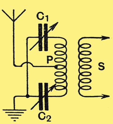
Fig. 2. - The balanced aerial circuit used in the Fleming AGC scheme.
Put briefly, Fleming utilises the change in current in the detector-anode circuit to detune mechanically at balanced aerial input circuit. In an aerial circuit arrangement such as that shown in Fig. 2, it the capacitors C1 and C2 are adjusted to perfect balance, there will be no transfer of HF energy from the primary P to the secondary S. If one of the capacitors, say C1 is unbalanced, the energy transfer will be proportional to the degree of unbalance.
Fleming takes advantage of this condition in the following manner: Referring to Fig. 3, there is connected in the output circuit of the detector valve, between the anode and the primary of the first LF transformer, a variable resistance R. Connections are taken from this resistance, as shown, to the winding of a sensitive galvanometer, the needle of which is mechanically coupled to the movable plate of the 3-plate midget capacitor C1, which corresponds to C1 in Fig. 2.
By pre-setting manually the variable tapping on resistance R, the degree of swing, or unbalance of C1, can be controlled, and the device functions in such a manner that loud speaker volume can never exceed the pre-determined level, even if the receiver is tuned through a powerful local station.
Galvanometer Scheme
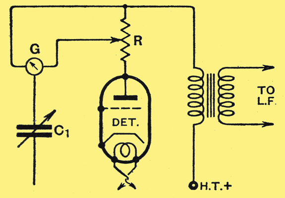
Fig. 3. - Method of application of the Fleming system of AGC. G is a sensitive galvanometer.
The circuit arrangements shown in Figs. 2 and 3 need not be adhered to rigidly; considerable modification is permissible to meet the requirements of the circuits of existing receivers which it is not desirable to disturb too greatly. The amount of energy required to operate the galvanometer naturally depends upon the design of the galvanometer; the inventor's existing experimental model gives a full-scale deflection on a maximum current range of 1 mA. Some form of light damping of the galvanometer and capacitor plate swing is desirable to prevent excessive mechanical oscillation.
In conclusion, it is claimed by one American manufacturer that practically every radio receiver in the future will have an overall sensitivity of the order of 5 μV or better. It is not only reasonable, he states, but necessary to apply to these receivers some method of control which will adequately deal with the signal inputs encountered in practical operation, ranging all the way from five microvolts to one million microvolts. Which sounds reasonable enough in a land where a few valves more or less are a mere detail of design and cost only three or four shillings a piece for replacement.
|
