|
The considerations governing the choice of valves for a straight set are well known. In the case of the superheterodyne, however, so many functions are allotted to the valve that it is a matter of some difficulty to make the right selection. The author, who is well known as the designer of a number of Wireless World superheterodynes with many original features, here discusses, among other points, how the different requirements of frequency changing and intermediate frequency amplification can be fulfilled.
The task of selecting the types of valve for the various stages of a superheterodyne is considerably more difficult than in the case of a straight set, if only because there are a greater number of different functions to be performed. In the straight set one is concerned merely with the straightforward processes of HF and LF amplification and detection, whereas in the superheterodyne there may be, in addition, the first detector, oscillator, and IF amplifier to consider.
The requirements as regards the detector and low-frequency stages are little different from those of any ordinary receiver, and. in fact, those variations which are sometimes found in practice are usually due more to the use of tone correction than to the employment of the superheterodyne principle. It is chiefly the and IF amplifiers, the first detector, and the oscillator with which we are here concerned.
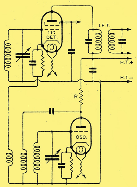
Fig. 1. - The circuit of a typical modern frequency changer showing the oscillator and first detector with mains type valves.
The function of the oscillator is simple; it has merely to provide a high-frequency current of the requisite amplitude and as free as possible from harmonics. A commonly employed frequency-changer circuit is shown in Fig. 1, and many types of valve will perform satisfactorily as the oscillator. In general, however, it is desirable to choose a specimen having an anode AC resistance of between 3,000 Ω and 10,000 Ω in the case of indirectly heated valves, and between 6,000 and 20,000 Ω in the case of battery-type valves. The difference is brought about by the lower mutual conductance of the latter type, which renders it inadvisable to employ a very low resistance valve on account of its low amplification factor.
Types represented by the 164V, the MHL4, and the AC/HL, or their DC counterparts, are suitable in the mains-operated class; while the PM2DX and the HL2 represent the best category of battery valves. The anode potential should normally be moderate and lie between 60 Volts and 100 Volts, while the negative grid bias should have the value which would be applied it the valve were acting as an amplifier. The anode current, however, will be greater than the rated value for the valve under those operating conditions by an amount depending upon the circuit constants and the DC resistance of the anode circuit.
The higher the DC circuit resistance, the smaller will be the increase in current due to oscillation, so that it is usually desirable to feed the anode circuit through a high resistance R of Fig. 1. A valve which normally passes an anode current of 5 mA may easily take 30 mA when oscillating if the circuit resistance be low, as in case where the HT is taken directly from a tapping on a battery. The insertion of a feed resistance may allow of satisfactory results being obtained with a current of no more than 7 mA.
The first detector acts as an anode-bend rectifier in practically every modern superheterodyne, but its action is not necessarily identical with that of the more familiar type sometimes used to teed the LF circuits. Its action is modified by the presence of the local oscillator, and it is linear when correctly operated. A high mutual conductance is desirable for the sake of efficiency, While a high internal AC resistance is necessary to avoid damping the tuned IF coupling connected in its anode circuit; moreover, the internal grid-anode valve capacity must be low in order to avoid. the signal frequency input tuned circuit being heavily damped by anti-phase feed-back. A screen-grid valve is thus obviously necessary.
The First Detector
When biased to the optimum rectification point, however, the valve must be capable of handling, without any flow of grid current, the maximum input which it is ever likely to receive; grid current might introduce distortion, and would certainly reduce the selectivity of the input circuit. The signal input will often be larger than one might at first expect. Not only will there be potentials due to the local oscillator and to the wanted signal, but when receiving a station on a wavelength close to that of the local there may be several Volts due to that local station. The sum of these various potentials will often be about 5 or 6 Volts, and, in consequence, the bias should not be less than this figure. In certain special cases the input voltage may be considerably greater, and the bias must then be correspondingly increased, The valve selected, therefore, must have such characteristics that, with the maximum rated values of anode and screen voltage, it requires a bias of at least 5 Volts for optimum rectification efficiency. This limits the choice to fairly low mutual-conductance types, and the MS4 and DS represent one of the most suitable classes among mains valves. A wider range is available among battery types, and the S21, S22, PM12, 215SG and SG215 should all be satisfactory. The use of variable-μ valves is not ruled out, and the possibility of applying a high value of grid bias, although at reduced mutual conductance, is a property which may prove increasingly valuable in the future.
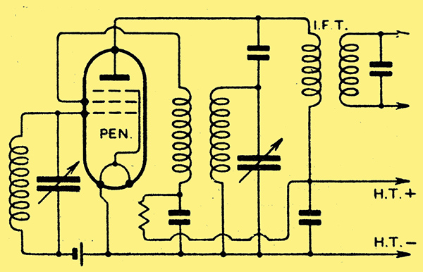
Fig. 2. - The connections of the self-neutralised pentode single valve frequency changer used in The Wireless World Baby Superhets.
Single-valve frequency changers offer far less scope for individuality in the choice of a valve, and, in the case of the bi-grid type, there is little possibility of variation, The case of the self-neutralised pentode circuit of Fig. 2 is somewhat different, however, but the requirements are rather stringent. The valve must oscillate freely with the appropriate circuits connected between its anode and space charge grid, it must have approximately equal control grid-anode and space charge-grid; anode inter-electrode capacities, must have a high internal AC resistance ,with the optimum operating potentials, it must function with a sufficiently high negative bias on the control grid to avoid grid current, and it must be silent in operation.
Pentode Frequency Changer
The majority of these requirements cannot be determined from the usual valve characteristic curves, and at present it is often necessary to rely upon trial and error. Most pentodes are satisfactory as regards their internal resistance, since this becomes high at the low screen potential at which optimum oscillation is secured. The grid bias required is appreciably less than with the usual frequency changer of Fig. 1, because the oscillator voltages are not applied to the control grid, and we have to cater only for the signal potentials. Although all the pentodes available have not been tried with this circuit, a large number have been tested, and only the AC/Pen, the MPT4, and the Pen220A have been found satisfactory on all counts.
We next come to the question of the HF valve, if such be included. The greater the amount of stable amplification which can be secured, the less important is background hiss likely to be, but the greater the risk of overloading the first detector when the set is tuned near the local station. A variable-μ type is essential, otherwise cross-modulation will make the stage worse than useless; in most cases it is better to dispense with it altogether than to use an ordinary screen-grid valve.
Variable-μ valves vary among themselves, however, and those with a low mutual conductance have usually the nearest approach to the desired characteristics. Although rather less amplification maybe achieved, therefore, this type is usually desirable in order to obtain the maximum immunity from the evil effects of cross-modulation and modulation rise.
In the lF amplifier there is usually no necessity, as regards cross-modulation, for the use of variable-μ valves, but they should normally be employed in order to secure a simple, effective, and distortion-less volume control. In this connection it should be pointed out, however, that although the variable-μ valve gives a control of amplification which is greatly superior to that afforded by any screen-grid type, it is not necessarily perfect. It is, in fact, quite possible for there to be serious distortion when it is used with a high bias voltage for reception of the local station. The matter depends largely upon the total amplification of the set, the manner in which this is obtained, and the way in which the bias voltages are graded in the different stages. It is quite possible to obtain a distortion-less volume control in almost any set, but the indiscriminate use of the variable-μ valve is not in itself a guarantee of this.
Where two lF stages are employed, the valves should definitely have low mutual conductances, otherwise stability may be difficult to achieve. Even with a single stage it is often advisable only to use a high mutual conductance type in cases where no preliminary HF amplification is fitted. The greater the amount of amplification following the first detector, the more serious is background hiss likely to be, and this places a definite limit to the amount of useful IF amplification which can be secured.
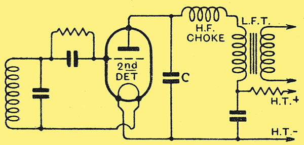
Fig. 3. - Anti-phase feed-back in the second detector is likely to be greater in a. superheterodyne than in a straight set on account of the higher reactance of the by-pass capacitor C.
The second detector differs in no way from the detector of an ordinary straight set, save that the damping on the input circuit due to anti-phase feed-back is likely to be greater. This is due to the fact that the bypass capacitor C, in Fig. 3, cannot have a higher capacity in a superheterodyne than in a straight set, on account of the necessity for preserving the higher audible frequencies. As a result, the detector load impedance at the intermediate frequency may be fairly high, and, in spite of the high reactance of the valve inter-electrode capacity, a considerable amount of feedback may occur. The valve chosen, therefore, should have as low a capacity as possible, but, as the effect is only of secondary importance, the valve should be selected chiefly for its other characteristics.
The LF and output stages are in no way different from the straight set as regards the choice of valve, and the usual considerations fully apply. Where the very best quality is desired, therefore, triodes will be selected for the output stage, and will be used in conjunction with an intermediate LF stage designed to give a low gain with a moderate degree of tone correction for any sideband cutting in the IF amplifier.
Tone Correction
In cases where economy is of importance, however, the possibility of using an uncompensated pentode output valve to provide automatic tone correction should not be overlooked. Such a valve may be fed directly, and, with a fully efficient coupling from the detector, and will provide, in most cases, as great a degree of tone correction as many of the special circuit arrangements. The use of a pentode in preference to a triode in a superheterodyne, therefore, leads to a considerable saving, not merely because of the greater sensitivity, but because tone correction can be secured without additional apparatus. A pentode may thus be a true economy, and its substitution for a triode will often give increased brilliance to the reproduction.
The disadvantage of a pentode, of course, is that it is more liable to introduce amplitude distortion than a triode when the circuit conditions are not exactly correct, and careful matching of the valve and loud speaker are essential. The output choke or transformer must have a higher inductance if distortion is to be avoided, and so these components will be of greater cost. Furthermore, the output of a pentode working under even the best conditions is likely to contain a greater percentage of harmonics than that of a triode.
The output stage is always rather a controversial question, but we may fairly say that where the best quality is desired it is advisable to choose triodes. Where the maximum of efficiency or economy is needed, while still retaining high-quality reproduction, a pentode should be used.
|