|
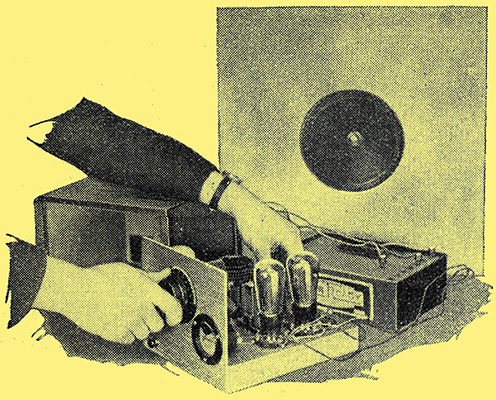
The Quiescent Push-Pull two. The Wireless World, January 20, 1933.
Further notes on operation and a review of components submitted for test.
Since the first constructional receiver embodying quiescent push-pull was described in this journal, a large number inter-valve and loud speaker transformers with characteristics suitable for this type of amplification have made their appearance on the market. From the wide variety of components available it is possible to make a choice to suit any QPP amplifier design with the knowledge that compromise can be avoided and that the circuit requirements will be fulfilled.
There are, for instance, a number of input transformers of different primary inductance and having ratios varying between 7 and 10 to 1, with the result that it is possible to apply the correct load to the detector valve in use and to ensure that the step-up ratio in the inter-valve coupling is sufficient on full modulation to load two output valves in QPP. Considerable attention has been given to the difficult task of matching the speaker to the QPP system, and manufacturers efforts have now been well rewarded. The constructor will find on the market a series of output transformers with which it is possible to obtain powerful signals of good quality from almost any loud speaker with a speech coil impedance varying between the wide limits of 2 and 2,000 Ω
Matching the Pentodes
Experiments with the Quiescent Push-Pull Two reveal that whereas the permanent magnet moving-coil loud speaker is undoubtedly the best reproducer for QPP circuits, really very pleasing results can be obtained with moving-iron instruments, provided that an output transformer of correct ratio be chosen. A special inter-valve transformer embodying a continuously variable tone control is being manufactured, and will be found of great assistance in correcting the attenuation of high notes caused by sideband cutting which occurs in the less ambitious type of set when reaction is pressed to the limit. Furthermore, it is generally found that at high volume levels speech is made much more natural if the tone is raised above that which is found the most pleasing with music.
Some twenty components and accessories for the Quiescent Push-Pull Two have been sent in for review, but before describing their performance a, few further hints on the initial adjustments of the receiver may not be out of place, especially as the process of matching the Pen220A valves was dismissed rather briefly in the original article.
First of all , it should be made clear that the anode currents of the two pentodes must be matched by adjusting their individual auxiliary grid voltages, using the 1½ tappings provided in the special QPP high-tension battery, care being taken to switch off the set while making alterations. The common anode lead is taken to the maximum HT voltage tapping on the battery (130½ Volts) and is left there permanently. Of the 16½ Volts of the bias battery only 14 to 15 Volts are required, and as a potentiometer control is provided, voltmeter readings of the actual bias applied are liable to be misleading. It is therefore necessary to judge the correct position of the slider by rotating its controlling knob to the extreme anti-clockwise position and then turning it back again about an eighth of its total travel or about five minutes if the arrow on the knob is regarded as the minute hand of a clock.
Having set the potentiometer and inserted the auxiliary grid wander plugs at random in the 1½ Volt tappings near the maximum positive end of the battery, remove one pentode from its valve holder and take a reading on the milliammeter of the anode current of the remaining pentode. By adjusting the appropriate auxiliary grid tapping (the coloured leads in the multiple cable facilitate the tracing of wires) and by very slight movement of the bias potentiometer, the correct current of 2 mA can be made to flow.
Next replace the idle pentode in its holder and remove the brother valve, again changing the auxiliary grid voltage tapping until about 2 mA flows, but this time the bias control must not be touched. As a final check the meter should show 4 mA for the total quiescent anode current of the output stage.
The constant resistance shunted across the bias battery causes it to discharge at such a rate that the voltage drops in sympathy with the HT battery. It would be advisable after a month or six weeks to check the matching of the valves and to see that the total anode current is 3½ to 4 mA. Although the meter must be short-circuited to prevent distortion while the set is working, it will be found to be of considerable value as an indicator of resonance when a note of constant modulation such as a tuning note from a local transmitter is being sent out.
At about thirty miles from Brookmans Park the tuning note can be made to increase the standing current from 4 to 9 mA before oscillation occurs. Those living nearer to this transmitter could probably obtain an increase-up to 12 mA.
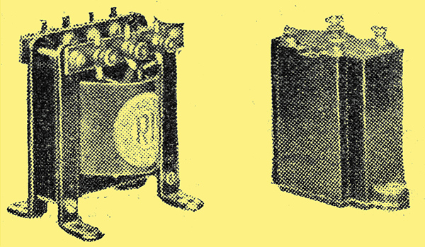
RI output (left) and inter-valve (right) components for QPP.
Of special interest to the constructor are the QPP components introduced by RI, Ltd. This firm has been investigating the merits of this latest development in battery-economy circuits for some months, and the inter-valve transformer designated the Q type, selling at 16s 6d, including royalty, was found to load the output stage adequately. The ratio is 1 to 8, and, although a nickel-iron alloy is used for the core, up to 3 mA may be passed through the primary. The inductance of the latter is 30 Henrys with no DC and 16 Henrys with 2 mA. The output choke of this series provides four ratios, namely 1 to 1, 1.4 to 1 and 2.8 to 1, and enables almost any high-impedance speaker to be matched correctly. Each half-primary inductance is 70 Henrys. This component is styled DY35, and sells at 12s. 6d.
QPP Chokes
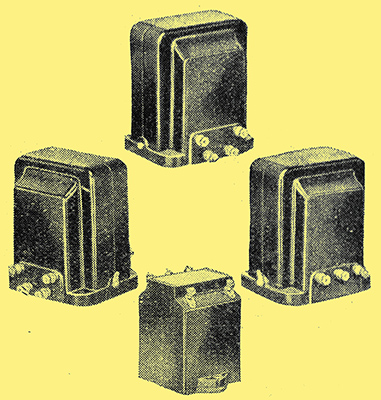
QPP inter-valve and output components manufactured by Varley. High or low resistance speakers can be matched.
The Varley range of QPP components include one input transformer and three output Transchokes, the latter providing every conceivable ratio for matching both high and low-resistance loud speakers; On test the inter-valve transformer gave an extremely good account of itself, and the high ratio of 9 to 1 ensures that the output stage just runs into grid current when the detector is giving its maximum output. This was easily proved by interposing an micro-ammeter in the common grid circuit. The primary inductance is 27 Henrys with 2 mA DC passing. The transformer is called the DP36, and sells at 17s 6d, including royalty.
Of the output devices marketed by this firm mention should be made of the DP37 Transchoke, giving ratios of 3 to 1 and 42 to 1 - the former for high-resistance speakers (or low-resistance speakers with built-in transformer) and the latter, for the low-resistance type in which the speech-coil impedance is 10Ω. The inductance of each half-primary is 13 Henrys when DC peak currents of 26 mA are passing. The price, including royalty, is 18s 6d. Other Transchokes provide ratios of 3 to 1, 50 to 1, and 75 to 1.
Multitone transformers and output choke. Tone controls available.
There are a number of Multitone transformers for QPP available, and one of which is particularly interesting is styled PUCO 1/8, selling at 17s 6d. By means of a special potentiometer connected across the centre tappings a continuously variable tone control can be obtained, which is, a valuable asset, for instance, with gramophone reproduction, where needle scratch and excess of Top can be successfully reduced. There are many other uses for this control, and it was found that when the transformer was used in the Quiescent Push-Pull Two reaction could be pressed considerably farther than hitherto, as the attenuation of high notes due to sideband cutting, could be compensated. The primary inductance is 30 Henrys with 2 mA DC passing. Other transformers in this range are the PU1/8, selling at 15s, and a high-quality transformer styled D4, with a ratio of 1 to 9 with the remarkably high inductance of 40 Henrys with 2 mA.DC. The price is 17s 6d. The Puchoke output-matching device provides ratios of 3 to 1, 1.5 to 1, and 1 to 1, and is intended for high-resistance speakers or for use in conjunction with speakers having a transformer already built in. Tested with a Blue Spot 66K high-resistance unit (moving iron), using the intermediate ratio, the output level was high and the quality of reproduction quite satisfactory.
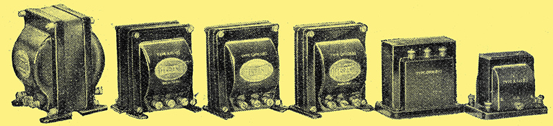
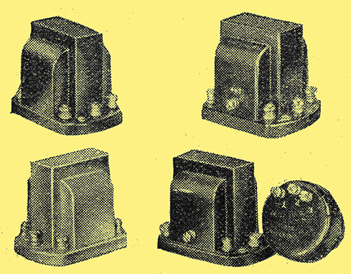
The Ferranti series of transformers, five of which have been specially designed for quiescent push-pull. The ratio of the output components ranges from 1.7 to 100 to 1.
Ferranti have just entered the market with a range of five QPP transformers, of which illustrations appear herewith. Unfortunately, they arrived just before going to press and there has not been sufficient time for a complete test, but from the enviable. reputation gained by this firm for the designing of push-pull transformers it can safely be assumed that the performance will be entirely satisfactory. Model AF11C is an inter-valve transformer with a ratio of 1 to 10, and an inductance of 50/27 Henrys when the primary current is 0 to 10 mA. The price is 34s, including royalty. There is an inexpensive input transformer known as the AF12C, with a ratio of 1 to 9, selling at 15s. In the output transformers type OPM13C is interesting, as ratios of 1.7, 2.7, and 4.5 to 1 are available, making the component suitable for use with high-resistance speakers or with the low-resistance type having a built-in transformer. The price is 26s 6d, including royalty. Another type OPM11C in this range caters for low-resistance speakers, and provides ratios of 35, 56, and 100 to 1.
Four permanetnt-magnet moving-coil loud speakers with special QPP transformers built-in have been received for review. In each example the speaker-transformer combination has been designed to impose a load of about 18,000Ω at approximately 256 Hz. In the case of the BTH RK Minor speaker the transformer has a very liberal core, ensuring high efficiency. The volume was rather greater than with any other speaker tested, and the tone was distinctly pleasing. Slight predominance of upper frequencies existed, but this was at once rectified by increasing the value of the capacitor in the compensator circuit across the transformer primary. It is called the QPP, and the price is 57s 6d.
New Speakers
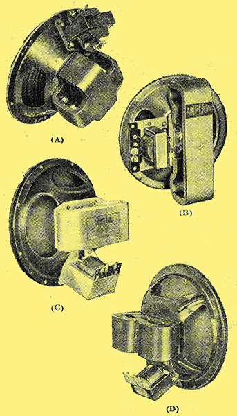
Four permanent-magnet moving coil speakers with special QPP transformers built in, (A) BTH RK Minor. (B) Amplion QPP. (C) Rola Type Q. (D) Earl Type QPP220A.
The Amplion speaker in this range (type QPP gave an entirely satisfactory perforrnance and was especially pleasing with music, the bass notes being well reproduced. The pentode compensator circuit with the original values unchanged should be used in this case. The price of the speaker is 39s 6d. A Rola speaker, type Q selling at 52s is available. On test The response was found to be substantially uniform over the musical range and the standard compensator was used.
Electriclocks and Radio, Ltd., are marketing the Earl QPP220A speaker embodying a transformer with nickel-alloy core. The reproduction is brilliant, and speech is exceptionally natural but with musical items it was found that the value of the capacity in the compensator circuit should be increased from 0.005 μF to 0.01 μF. At 35s, this speaker represents good value for money. A new QPP high-tension battery - the Ever Ready Type W1198 - has just made its appearance, and is tapped at the appropriate 1½ Volt intervals. The price is 12s 6d.
It is interesting to note that this specialised type of push-pull output is finding its way into commercial receivers, and among the pioneers who have adopted this design may be mentioned the Consolidated Radio Co, Ltd.It is hoped to deal shortly with the advantages of triodes in QPP.
|