|
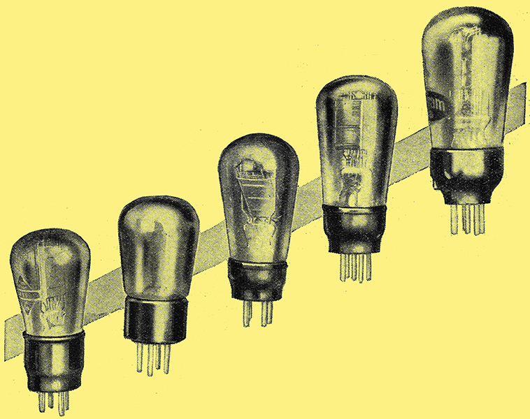
Valves suitable for QPP output. From left to right: Cossor 220PA, Mullard PM2A, Osram P2, Mazda Pen220A and Osram PT2.
Up to the present the principles of quiescent push-pull have been applied to pentode valves, and outputs of over one Watt have been obtained for an exceedingly small HT battery consumption. Where, however, the or consideration is valve cost rather than power output, triodes in QPP will probably find wide application, especially as matching is not essential and moving-iron speakers can be used satisfactorily.
Now that the great benefits conferred by quiescent push-pull are becoming appreciated, there must be many constructors who contemplate building a QPP receiver, or who propose to modify the output stage of their existing battery set. The desire to share with the mains user the undoubted advantages of a moving-coil loud speaker is natural enough, as is also the demand for more and more undistorted energy from the output stage.
True, the valve manufacturers not long ago gave us an excellent series of two-Volt power valves capable of handling a few hundred milliwatts, but until the advent of QPP, a wide gulf has separated mains output from that given by the battery set.
QPP and Mains Sets
Many queries have arisen as a result of the publication in this journal of the theory and practice of pentodes in QPP, and it is proposed to deal with a few of them. First, it is asked whether automatic grid bias can be arranged - the answer in the negative, because a fixed bias point to each valve is essential, and as the mean anode current during modulation varies between wide limits, large changes in grid potential would take place. Can QPP output be included in a sets with which an HT eliminator is used? The answer must be in most cases 'No,' because the HT Volts delivered by the eliminator vary in sympathy with the current taken, and a steady anode voltage - a desirable condition - would be denied to the valves. In eliminators where the regulation is especially good it would be worth a trial.
Can QPP find application in a mains set? The answer to this is governed by the answers to the two previous questions. It would be possible only with battery bias or with a small separate rectifier for grid potential and an HT supply system such as a mercury rectifier, with which regulation can be beyond reproach. There are two other important questions, but happily the answers are less gloomy. Can matching of valves in QPP be dispensed with? Are triodes in QPP satisfactory? The rest of the article will be devoted to discussing these problems.
Considerable research has been carried out by the General Electric Co. into the possibility of using triodes in QPP, and the writer is indebted to this company for certain data in respect of these valves which is given later. Any QPP system benefits if matched valves are employed, and the circuit of the Quiescent Push-pull Two receiver recently described probably represents the most efficient arrangement, but unless the very utmost is to be squeezed out of each valve, liberties can be taken. In fact, it is found that with triodes and the smaller pentodes, valves bought at random and representing the extremes of manufacturing tolerances may be pressed into service with the knowledge that the results will be entirely satisfactory, and a milliammeter, although most helpful, is not essential.
Experiments with Two Receivers
Two receivers have been constructed, one with two Osram LP2 valves in QPP, and the other with two P2 valves. From the results obtained it can be stated with confidence that the volume and quality of reproduction will satisfy the most critical. Unmatched triodes are essentially for use where the major consideration of valve cost outweighs power output. In a room measuring, say, 15ft by 15ft, a Watt of speech energy is unnecessary, and 350 to 400 milliwatts provides good entertainment. The two LP2 valves at 150 Volts H T will give this output for the ridiculously small consumption of 1[m]mA standing current per valve. The detector will feed the output stage without an intermediate valve, use being made of one of the high-ratio inter-valve transformers developed for QPP. Although the best results will be obtained with a moving-coil speaker, the use of a moving-iron instrument is not ruled out.
The load per valve is 5,000 Ω, so that the output transformer ratio is almost the same as that for two Pen220A valves, for which so many speakers and output devices are already available. There is a very slight tendency for high notes to be accentuated, but this is cured by the ordinary compensator circuit consisting of an 0.005 μF capacitor and a 20,000 Ω resistance in series, the whole being shunted across the output transformer primary. The 150,000 Ω anti-parasitic resistance in the common bias lead must be retained and a potentiometer across the grid battery (9 to 10½ Volts in this case) is a refinement which is well worth while.
In all cases where a meter is not embodied in the set it is as well to move the bias potentiometer slider to a position of over-bias, thus giving serious distortion and then to reduce the negative grid potential slowly until distortion on loud passages is absent. This will automatically give the correct quiescent or standing current, and the valves will be working under optimum conditions. It will be unnecessary in the circumstances to have a battery tapped at intervals of 1½ Volts at the positive end.
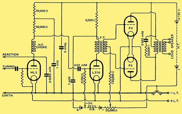
Fig. 1. - The detector LF portion of a receiver with two P2 valves in QPP. In this case an intermediate LF stage is necessary and the inter-valve transformer ratio should be about 4 or 5 to 1.
The circuit diagram showing the detector LF portion of the set with two un-matched Osram P2 Valves (triodes) in QPP is given in Fig. 1, and as the grid swing of the output system in this case is about 21 Volts the detector must be followed by an intermediate low-gain resistance-coupled,stage. Fortunately, this is an economical addition, incurring about 11s in cost of materials and augmenting the anode current by only 1 mA. The output from the set amounts to about 800 milliwatts, which represents ample volume for a room measuring about 14ft by 25ft, and again the quality of reproduction is very pleasing.
As all values are given in Fig. 1, further details of the set will be unnecessary, but emphasis should be laid on the tremendous saving in HT current effected by the QPP stage. It would require over 40 mA from the HT source if two P2 valves were used in ordinary push-pull to give the same output. Actually, in the set under discussion, the standard current per valve is 2 mA, and the working current - which is the deciding factor in choosing the capacity of the HT battery - only 7 mA total for the two valves.
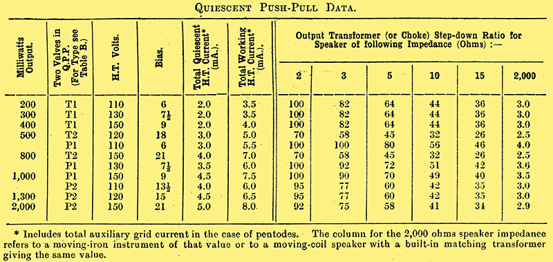
Table A
To facilitate the choice of a suitable valve for a given output, Table A has been compiled, which includes the majority of British battery valves which can satisfactorily be used in QPP T1 and T2 represent triodes and P1 and P2 pentodes, the key to the types of different makes being given in Table B.
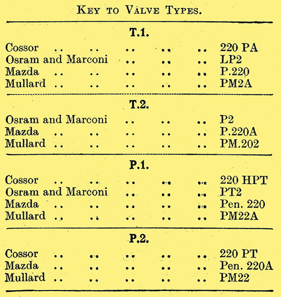
Table B
The HT battery should have an initial potential of about 10 Volts higher than the figure given in the third column, so that it will settle down after short use to the required value. If the bias necessary (4th column) is above about 15 an intermediate RCC stage will be required before the output valves, and it can well conform to the circuit of Fig. 1. The total quiescent current is given in the next column, and includes in the case of pentodes the two auxiliary grid currents. It is interesting to note that the average working current seldom reaches twice the value of the quiescent current, although peak currents on deep modulation may reach five times this value.
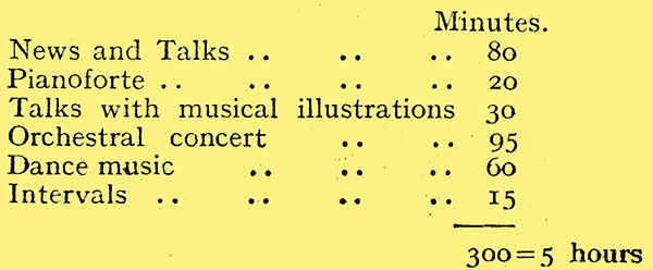
The reader may be, somewhat surprised at the low average HT consumption, but when it is realised that appreciable current is taken only when a signal is being received, the reason will be clearer, especially if the composition of a typical five-hour broadcast programme be examined. The following is part of a continuous evening's programme during which QPP current measurements were made. Speech and intervals accounts for 125 minutes, during which little current is used.
The remaining columns of Table A are devoted to the step-down ratio which must be used in the output transformer with speakers of different impedance. With 2 Ω speech coils, which are popular to-day, the theoretical ratio in at few instances is more than 100 to 1 but as such transformers are not made no ratio exceeding this value is shown. To exemplify the use of the tables, let, us suppose that an output of 400 milliwatts is required from a moving-coil loud speaker of 10 Ω impedance (we will assume that the built-in transformer - if the speaker has one - is disconnected). A valve of Class T1 would be chosen, the HT voltage must be initially about 160, the bias 9 Volts, and no intermediate LF stage is necessary. The transformer ratio should be 44 to 1 - the nearest standard ratio of 42 to 1 being quite satisfactory. With a moving-iron speaker of high resistance (say 2,000 Ω) the ratio would have to be 3 to 1.
Fortunately the ear does not notice slight mismatching of the output stage, and where ratios between, say, 68 or 82 to 1 are indicated, a transformer of 75 to 1 would be perfectly satisfactory. Many output devices with ratios between 1 to 1 and 100 to 1 were reviewed in an article entitled 'More About the Quiescent Push-pull Two' and there should be little difficulty in selecting suitable components.
|