|
In this series of articles the path of the signal through the circuits of the superheterodyne receiver is explained stage by stage.
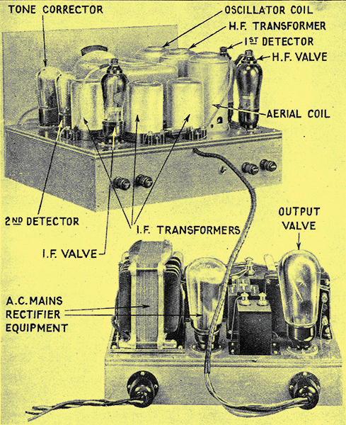
Illustration of a typical superhet, The Wireless World Monodial, with the various parts identified.
Choosing a square-law valve.
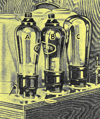
The first detector (B) is here shown mounted between the HF valve (A) and the oscillator (C).
In this article, which is the fifth of the series, the first detector is discussed. It is probably not generally realised how widely this detector differs in its action from the type used in a straight set. As the input consists of both the signal and oscillator voltages the principle of demodulation arises and plays an important part.
The chief operating principles of the superheterodyne will now be apparent, and we can turn our attention to the details of design upon which so much depends. Let us return first to the frequency changer. The necessity for using a diode or power grid detector for high-quality reproduction has been so often stressed in the pages of this journal that a lack of confidence in the ability of the superheterodyne to deliver an output free from distortion is often expressed, since anode bend rectification is almost invariably used for the first detector. It is not generally realised, however, that the operating conditions of the first and second detectors are in no way parallel. So far from an anode bend first detector introducing distortion, it is probably the only rectifier which will permit distortion-less frequency changing.
The ordinary detector is usually considered to have an input from the desired station, that is, a single modulated carrier, and no account is taken of interference. In this case, a linear rectifier is essential if the modulation is not to suffer amplitude distortion. A rectification characteristic which is linear for a single applied voltage, however, is not necessarily linear when two or more voltages of different frequency are simultaneously applied to the rectifier. It has, in fact, been pointed out by F M Colebrook that when two signals are applied to a linear detector the effective rectification characteristic is profoundly modified; the characteristic becomes non-linear. If the two signals are of different amplitudes, the rectification characteristic for the weaker of the two departs considerably from the original straight line and the efficiency of rectification is greatly reduced. As far as the stronger signal is concerned, the characteristic is much less affected, and the efficiency and linearity are only slightly reduced.
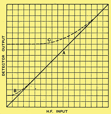
Fig. 1. - Rectification characteristics (A) for a perfect detector with a single input voltage, (B) for the same detector to the stronger of two simultaneously applied voltages, and (C) to the weaker of two applied voltages. The large change in the last case should be noted.
The effect is, perhaps, best illustrated by the curves of Fig. 1, in which curve A shows the rectification characteristic, that is, the detector output plotted against the input, for a perfect rectifier operating with a single input voltage. When two different inputs are simultaneously applied, the characteristic is modified, and takes the form shown by curves B and C. If one signal be much stronger than the other, the characteristic for the strong signal is very little affected by the presence of the weaker, and is similar to curve B, The response of the detector to a weak signal in the presence of a stronger, however, is shown by curve C, and it is evident that the characteristic has been very greatly modified. The slope of the curve is greatly reduced, indicating poor efficiency, and it is far from the ideal straight line. The effect is the well known apparent demodulation of a weak signal by a strong.
Now the first detector of a superheterodyne never operates on a single input, the ideal case for the second detector, for there is always one voltage due to the signal and another from the local oscillator. Under normal conditions the voltage from the oscillator is stronger than. that caused by the incoming signal. If we use a linear first detector, therefore, the effective rectification characteristic to the signal will be similar to curve C of Fig. 1; it will be very far from linear. The process of frequency changing, therefore, will not only be inefficient, but it will introduce distortion and may also be responsible for whistle interference.

Fig. 2. - The square-law detector has a curve such as (A) for a single applied voltage, but to the weaker of two simultaneously applied voltages it takes the form of (B). Under the correct condition, the first detector is thus linear.
Suppose, however, that instead of using a linear detector we employ one of the square-law type. For a single input the characteristic will then be a curve such as A of Fig. 2, and at first sight it appears to be quite unsuitable. In the presence of the local oscillator, however, it takes a different form just as the characteristic of a linear detector becomes non-linear in the presence of the oscillator, so the response of a square-law detector becomes linear to the weaker of two simultaneously applied voltages, as shown by curve B.
Detector Overload
In practice, valve curves do not follow a square law over the whole of their range, and, as the input voltage increases, they approach more closely to a straight line. This is shown by curve A of Fig 2, which follows a square law only for small input voltages. As a result, the effective rectification characteristic of a practical first detector is only linear as long as the input does not exceed a certain value. For large inputs, when the valve curve is approaching linearity, the effective characteristic begins to droop and becomes non-linear. This is brought out by the bend in curve B of Fig. 2.
In designing a superheterodyne, therefore, we must always keep the first detector input below the value at which non-linearity commences. Quite a large latitude is permissible, and in a receiver of the type which we are discussing the second detector will normally overload long before the first detector approaches non-linearity.
The conditions which we have discussed, however, are only those of the reception of a single station with the sensitivity of the set adjusted appropriately to its strength by the volume control. Practical conditions will often be much more severe, and the first detector input will certainly not be confined to voltages from two sources only,the desired station and the local oscillator. Suppose that we are trying to receive a weak signal spaced by only 20 kHz from a powerful local, and for the reception of this weak signal the set must be working at its maximum sensitivity. With an efficient aerial the local station may set up as much as 7 Volts peak, across the aerial tuning capacitor (see Cr, Fig. 1, in the first article of this series) when this circuit is tuned to resonance. Even if the aerial tuned circuit be efficient, there is unlikely to be less than 1 Volt peak applied to the grid of the HF valve when this circuit is mis-tuned from the local by only 20 kHz.
Volts from the Local Station
If the inter-valve tuned circuit is of similar efficiency, and the stage gain at resonance be 100 times, the amplification of the local station will be 15 times, so that there will be 15 Volts peak due to the local applied to the first detector grid in addition to the minute potential from the wanted station and the oscillator voltage. During deep modulation the peak voltage from the local station may rise to nearly double this value. The oscillator voltage should always be stronger than any other potential applied to the first detector, so that for this condition the first detector should be biased to not less than 60 Volts negative, it grid current and consequent damping of the tuned circuit and overload distortion are to, be avoided.
This condition, of course, is absurd, for it would necessitate the use of a large output valve tor the first detector. This is impracticable but it would theoretically be necessary under the conditions laid down. These conditions, however, are unnecessarily severe, for if the wanted signal were so weak that the full amplification of the set were necessary with a good aerial it would be weaker than the generally prevailing level of background noise due to atmospherics, and so be of little use. In general, the wanted signal will be much stronger, so that the full amplification is not needed with a good aerial. Suppose that the station has a strength such that an amplification of only 25 times is needed from the valve, or only one-quarter of the maximum value. The maximum peak input to the first detector on deep modulation from the local station will then be no more than 7½ Volts, and the bias can be some 15 Volts only. This is quite a possible case, but not one which is often encountered in these days of powerful transmitters, for a bias of some 6 to 10 Volts is usually sufficient. These examples, however, show the need for care in selecting the operating conditions of the first detector, and it is evident that this valve should be operated with as small a signal input as possible. We have the question of background hiss to consider, however.
It is well known that a hissing sound is evident when an ordinary reacting detector is oscillating, and the same effect sometimes occurs in a superheterodyne. The output of an oscillator is not a pure HF current, for it carries a slight modulation due to imperfections in the circuit and valve. The amount of such modulation is very small, and very high amplification is necessary before it becomes audible. Nevertheless, it places a definite limit to the amount of useful amplification which can be used following the first detector of a superheterodyne. A slight hiss during pauses in the wanted modulation may be unobjectionable, but when it is evident at a strength comparable with that of the programme it is intolerable.
The amount of IF amplification which can be usefully employed is at the present open to doubt. It depends largely upon the purity of the oscillator output as regards the unwanted hiss modulation, but also upon the amount of LF amplification used, the volume level desired, and the degree to which high-audible frequencies are retained. In general, more than a single IF valve leads to excessive background, but if the LF amplification and the maximum volume be moderate, two IF stages may be permissible; This applies, of course, to stages used to provide their maximum amplification, for two low-efficiency IF stages may lead to no more hiss than a single high-efficiency stage.
Since the lF amplification is limited, the sensitivity also is limited, unless HF amplification be employed. It will be seen, therefore, that the HF stage of a modern superheterodyne is used largely to obtain freedom from background hiss while keeping the sensitivity at a high level. If it were not for background hiss it would be simpler to provide the requisite if amplification at the intermediate frequency.
The use of an HF stage is by no means universal, however, and very many sets without it are to be found. In general, a superheterodyne Without an HF stage is less sensitive than one employing signal-frequency amplification, and in the reception of any given station it will tend to give more background hiss. This does not necessarily mean that the hiss will be audible, however, for that depends on the signal strength and upon the aerial employed. With a good aerial it is quite possible to obtain hiss-tree reception of the stronger distant stations without using an HF stage, but a set which does include such a stage will permit better reception of weaker stations, or as good reception of the same stations with a poorer aerial.
Reducing Input
We must now leave the first detector for the time being, but before doing so it is as well to emphasise that this valve must always be operated in a linear condition. As a result, either the valve must be of a type which will accept a large bias and still have a square-law characteristic, so that grid current does not flow when receiving a station nearby the local, or some means must be provided for reducing the input from the local station below the value which has so far been assumed to be a minimum in this article.
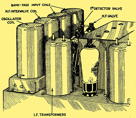
Typical arrangement of components associated with the signal frequency and oscillator voltages, which together must be applied to the first detector.
Series Contents
|