|
In this series of articles the path of the signal through the circuits of the superheterodyne receiver is explained stage by stage.
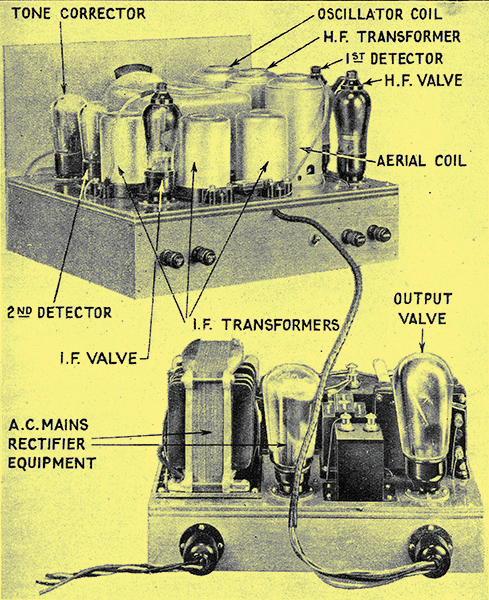
Illustration of a typical superhet, The Wireless World Monodial, with the various parts identified.
The Action of the Second Detector.
This, the fourth article of a series on the theory of the superheterodyne, explains why selectivity is so it greatly improved if tuned circuits resonating at a comparatively low frequency (the IF wavelength) are used. The problems of sideband attenuation and subsequent tone-correction are also covered.
In the preceding instalments little mention has been made of the selectivity of the intermediate frequency circuits, and as this is the raison d'étre of the superheterodyne it is fitting to give the matter considerable attention. Let us suppose that we have the carrier of the wanted station on 1,000 kHz, and that there is an interfering station on 1,010 kHz. The aerial tuned circuit favours the wanted carrier, so that on the grid of the first valve the wanted carrier is stronger, relatively, to the unwanted, than it was in the aerial. Similarly, the inter-valve coupling again favours the wanted carrier, and, as a result, the disparity at the first detector grid is increased.
This, of course, is the normal selective action, and if the wanted station be weaker originally than the interference, very many tuned circuits would be necessary if amplification were carried out throughout at the signal frequency, when this has a high value. Changing the frequency to a lower value, however, gives us a great gain. The intermediate frequency for the wanted carrier becomes, as before, 110 kHz, and that for the interfering station 100 kHz. The difference is still 10 kHz, and at first sight there appears to be no advantage. The gain is to be found, however, in the fact that the selectivity of a tuned circuit, expressed in the practical form of its power of rejecting a current at a fixed frequency different from resonance, increases as the resonance frequency becomes lower. For equally efficient circuits at all frequencies, the power of rejecting an unwanted station spaced from the wanted one by a fixed percentage frequency difference is a constant. Thus, at 1,000 kHz a station on 1,010 kHz is 1% off tune, but at 110 kHz a station on 100 kHz is nearly 10% off resonance.
Selectivity with Quality
With circuits of equal efficiency, therefore, one tuned to 110 kHz is as effective in rejecting a station on 100 kHz as would be a circuit tuned to 1,000 kHz in rejecting a frequency of 1,100 kHz. The vast improvement to be obtained in selectivity through the use of a low resonance frequency for selective circuits can readily be seen, for the effect is really to increase the percentage frequency separation of stations.
The question of quality of reproduction must be considered, however. Although from the point of view of interference a station spacing of 10 kHz at the intermediate frequency is equivalent to a spacing of 100 kHz at the signal frequency, the sidebands occupy a proportionately large range. They still spread by only about 5 kHz on either side of the carrier, but the IF tuned circuits are likely to attenuate them much as signal frequency circuits would reduce a sideband spread of 50 kHz. The problem of selectivity without sideband cutting in an IF amplifier, therefore, is similar to the reception of a carrier of 1,000 kHz, modulated by a frequency of 50,000 Hz. Unless we are very careful we shall find that the high intrinsic selectivity is not an unmixed blessing, for it will be accompanied by a serious degree of sideband cutting.
A series of tuned circuits on the broadcast band is not usually productive of very great sideband cutting, even if the bandpass principle is not employed. On the intermediate frequency, however, it is usually entirely prohibitive, and special circuit arrangements become necessary.
Type of Resonance Curve
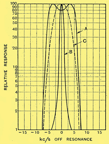
Fig. 1. - he type of resonance curve to be expected in an IF.amplifier. Curve A is for a purely band-pass receiver; curve B for a very sharply tuned amplifier; and curve C for a semi-band-pass arrangement.
One method is to use band-pass filters in order to obtain an overall resonance curve for the receiver which is substantially flat-topped with very steeply sloping sides, as shown in curve A of Fig. 1. Another method is to permit sideband cutting to take place, and to correct for the attenuation of high notes in the LF amplifier; the type of resonance curve then found is shown by curve B. The third way out of the difficulty aims at a compromise between these two, and this is the one adopted in the receiver of Fig, 1 of the first instalment of this series. The IF circuits are adjusted to give a characteristic passing only a narrow band of frequencies without attenuation, and tone correction is employed to restore the moderate loss of high notes which results. This type of resonance curve is shown by curve C.
The choice between the different methods will depend largely upon circumstances, and no definite ruling can be given. The full band-pass circuit is probably too difficult to adjust without special apparatus, and it is chiefly suitable for manufactured sets. Full sideband cutting is usually prohibitive when the required selectivity is obtained by ordinary means, although it is not necessarily so with special circuits, on account of the difficulties of tone correction. In general, for home constructed sets, the middle course is the wisest, and it readily permits both high quality and selectivity to be obtained.
It will thus be seen that the input to the second detector of the receiver described in the first article consists of a voltage due to the desired signal, which still carries the original modulation. The modulation, however, has been affected by the passage through the receiver, and the higher musical frequencies are represented much less strongly.
Diode Action
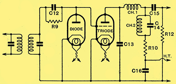
Fig. 2. - A simplified diagram showing the action of the second detector split between two valves. The tone-correction circuit in the anode of the triode should be noted.
The action of the detector is quite complex, for it rectifies, amplifies, and provides tone correction in conjunction with its associated circuits. It is by no means difficult to understand, however, if considered from the viewpoint of the circuit of Fig, 2. In this illustration two valves are shown doing the work which is normally performed by one; in the actual circuit of Fig. 1 (first article), the anode of the diode and the grid of the triode are the same electrode. The IF voltages developed across the secondary of the last IF transformer are applied simultaneously to both valves, through the grid leak and capacitor R9 and C12.
Rectification occurs in the diode, and, as a result, there is a direct current flow round its anode-cathode circuit. This current flows through the grid leak R9, and there is consequently a voltage drop across it in such a direction that the anode takes up a potential negative with respect to the cathode. Since the grid of the triode is joined directly to the diode anode, and the cathodes of the two valves are common, the triode grid is also biased negatively. When a signal is applied, therefore, the steady anode current of the triode is reduced, and in practice this may readily be seen by connecting a milliammeter in the anode circuit of the detector. In addition to the steady direct current through the grid, leak, there are also currents of the modulation frequency, which in turn set up alternating voltages across this resistance. These are applied to the grid of the triode, and cause corresponding variations in the anode current of this valve. In the output of the triode, therefore, we have a whole series of currents of different frequencies to sort out, just as we had in the case of the first detector.
In this case we require only the modulation frequencies, and neither the direct nor the IF currents are of any use to us. The direct current causes no trouble, but a filter is required to prevent the IF currents from reaching the later circuits, and, accordingly, the choke Ch1 and capacitor C13 are introduced. For the best results their values should be such that the choke offers a high impedance to currents of the intermediate frequency, and the capacitor has a low reactance at that same frequency.
If a large capacitor be used for C13, the load impedance ot the triode to IF currents will be small, and only a small lF potential can be developed in the anode circuit. As a result, only a small current can be fed back to the grid of the valve through the inevitable capacity which exists between the grid and anode electrodes. The tuned grid circuit, therefore, will not be damped, and its full efficiency will be maintained.
Tone Correction

Fig. 3. - Curve A represents the effect upon quality of the sideband cutting of the receiver, while curve B shows the required shape of tone-correction curve to compensate for this. Curve C is the result of combining the two.
It is found in practice, however, that when the capacity is large enough for this to occur it seriously attenuates the higher modulation frequencies. These are already weak, and require abnormally high amplification, so that the effect is inadmissible. In general, therefore, we shall have to choose a value for this bypass capacitor small enough to have no appreciable effect upon the modulation frequency response, and tolerate quite a large damping of the tuned circuit.
The general shape of the overall response curve of the receiver, as far as the second detector, is of the form shown Fig. 3 (curve A), and it will be seen that there is a serious loss of high notes. If this is to be avoided in the overall response it is obvious that the coupling between the, detector and the following valve should have a response curve which is the inverse of this one (curve B), so that the final result will be a straight line, curve C.
If we use a simple form of impedance coupling, the amplification given by the triode action of the detector, Fig. 2, will depend upon the value of the valve load impedance at that frequency. We can, therefore, make the amplification vary with frequency by the simple expedient of choosing a circuit the impedance of which varies with frequency in the requisite manner. A parallel tuned circuit in series with a resistance will do this. The load impedance to modulation frequencies, therefore, consists of the choke Ch2, which has a definite value of resistance, the parallel capacitor C14, and the resistance R10. At very low frequencies the reactance of C14 is high, and that of Ch2 negligibly small. At these frequencies, therefore, the coupling simply consists of R10 in series with the DC resistance of the choke, and for the values shown is about 1,400 Ω.
Overall Response Curve
The valve has an internal AC resistance of some 10,000 Ω, with an amplification factor of 35. The amplification at low frequencies, therefore, is about 4.3 times; quite a low value. As the frequency is increased the impedance of the tuned circuit rises, but it does not change greatly until 2,000 Hz is reached. Up to this frequency, therefore, the amplification remains substantially constant. When this frequency is passed, however, the impedance rises rapidly until it reaches its maximum at about 5,000 Hz, after which it again falls off. At 5,000 Hz the parallel tuned circuit has a dynamic resistance of about 22,500 Ω, and with the 1,000 Ω series resistance this means a total load impedance of 23,500 Ω. At this frequency, therefore, the amplification is about 24.5 times.
It will be seen, therefore, that, as a result of this non-uniform stage of amplification, correction is obtained for the sideband cutting which has been permitted in the IF and signal frequency tuned circuits. The overall response curve to the output of the second detector, therefore, is substantially a straight line over the range of modulation frequencies up to 5,000 Hz. All subsequent amplification must obviously apply to all frequencies equally so that the overall response curve will still remain flat.
The potentials appearing across the load impedance of the detector are transferred to the grid of the following valve by means of a capacitor and resistance C15 and R12, and this valve is itself coupled to the output stage by means of an transformer. These circuits differ in no way from those employed in any ordinary straight set, and they have been fully described many times in the pages of this journal, so that no useful purpose would be served by treating them here. This remark applies also to the decoupling circuits, the mains and other associated equipment.
We have now examined in some detail the purely superheterodyne portion of the apparatus, and have traced the course of a signal in the aerial to its appearance as a series of low-frequency currents in the anode circuit of the second detector. The fundamental operating principles of the superheterodyne, therefore, should by now be clear, and we can proceed to a more detailed discussion of a number of the more important design considerations.

The components associated with the second detector and tone-corrector stages of a superhet.
Series Contents
|