|
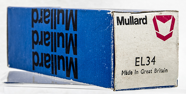
The EL34 arrived in the original box.
This broken EL34 was part of a donation by G8HCZ. The stylised M logo first appeared in 1970 dating this valve to that time or later The top of the tubular envelope is complete and the lettering shows a British made valve.
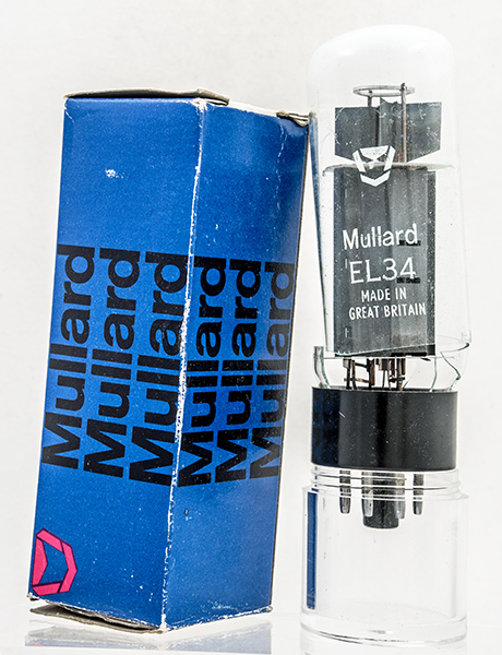 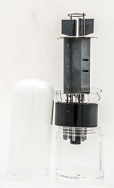
The valve removed from the box. The lettering is harder to see without the dark anode behind.
The EL34 replaced the 1946 EL37 as Mullard's 25 Watt dissipation audio output pentode in 1952. The EL37 was built on a standard pinch whereas the EL34 was of all glass construction with wires rather than pins. The wires being soldered into the octal base pins.
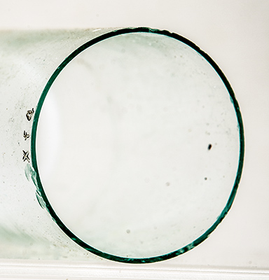 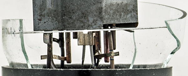
Left: the tubular envelope. Right: lower mica and connections.
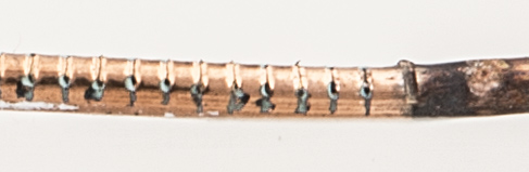
The main envelope tube is 0.7 mm thick and is made of a soft glass. The lead-out wires are held in a disc of hard glass and the two parts are melted together in final assembly. As the soft glass melts at a lower temperature than the hard borosilicate glass it joins to the base without distorting it.
The hard glass base starts out as a small section of tube that is formed into a disc around the multipart leads and internal supports. The central portion, the remains trapped in the glass is formed of an alloy (Dumet) that has the same coefficient of expansion as the glass and thus stays in contact. A coating allows the glass to 'wet' the metal.
Top mica and getter ring.
The getter holder ring is at the top and takes the form of an open channel. During evacuation of the valve RF heating raises the ring to a high temperature and the getter is deposited on the inside of the glass to mop-up any remaining gas molecules.
 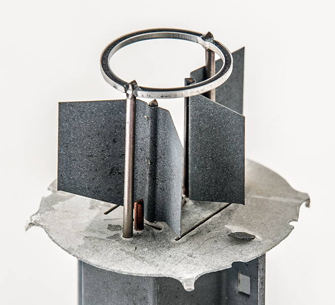
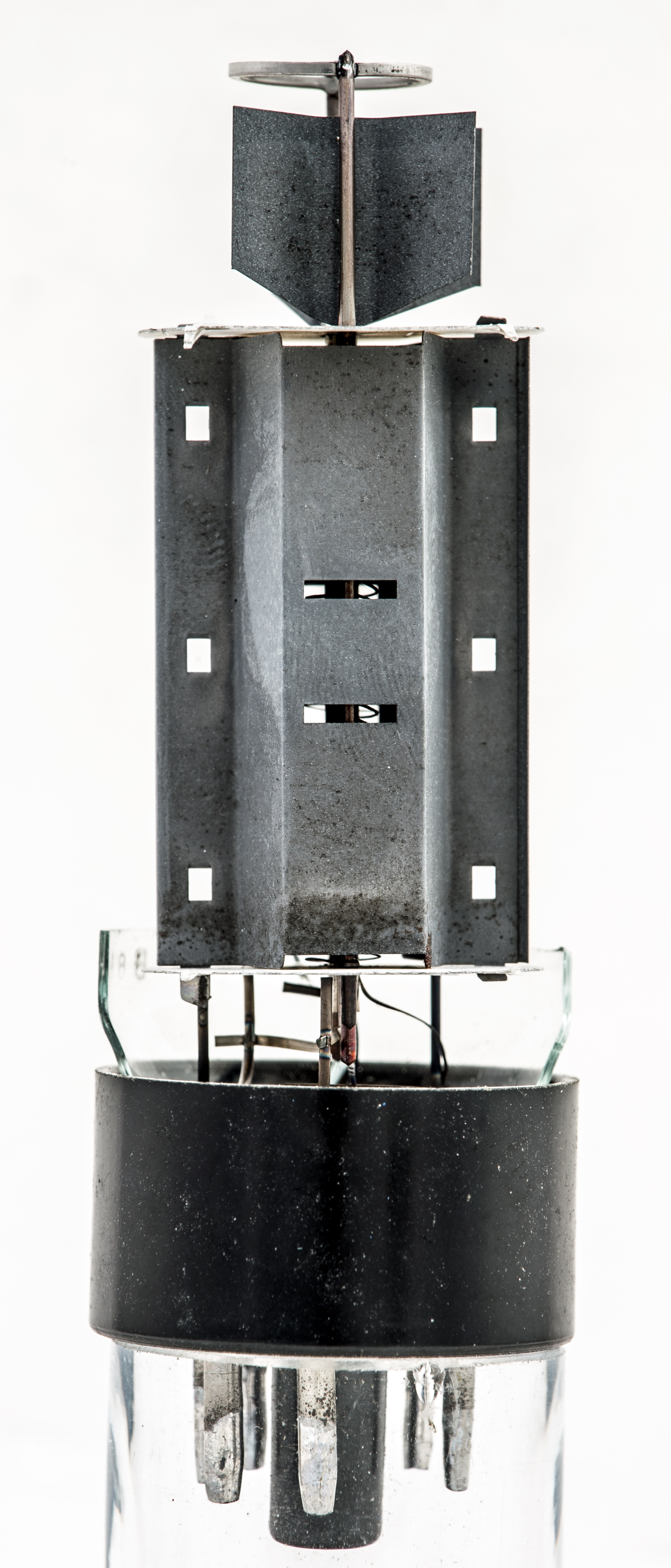
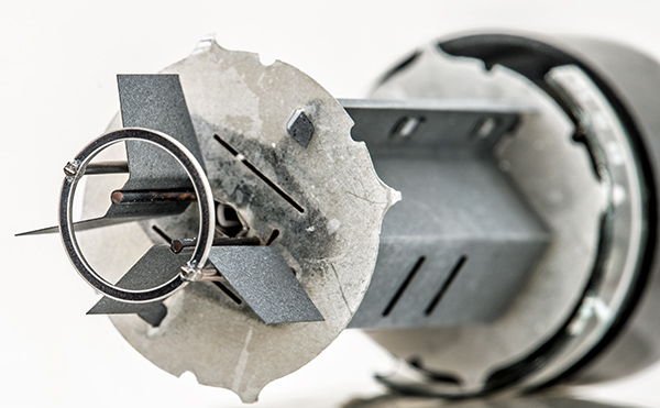
Top mica components, getter ring and control grid cooling fins.
Before breaking into the pentode assembly, a series of photographs were made to allow a close look at the structure. The fins at the top of the control grid are 0.13 mm thick and 12.5 mm tall.
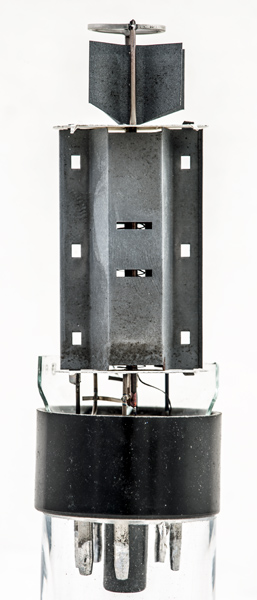 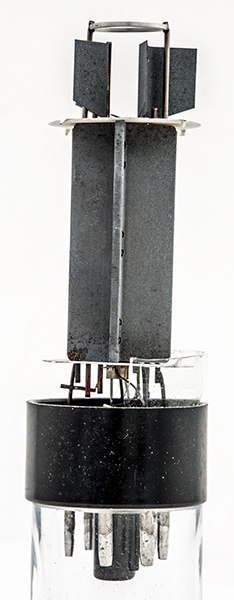
Two views of the pentode section. The left image expands to full size.
Side cutters were used to separate the wires above the top mica so that the mica disc could be removed. The anode has small tags top and bottom that fold over onto the micas.
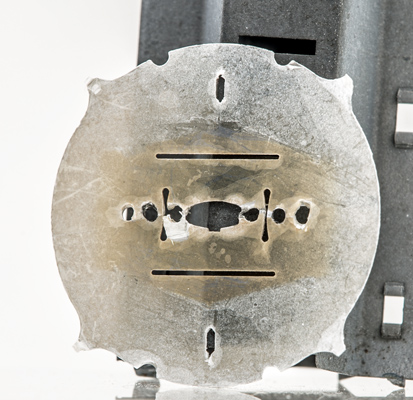
The top mica.
In the above image the slots top and bottom are where the anode lugs pass through the disc. The shape of the cathode tube is clear to see as are the three holes for the grid supports. The control grid supports are 6.5 mm apart, g2 supports are 10.5 mm apart and the suppressor grid holes are 14 mm apart.
The anode showing the fixing lugs.
The thin sheet nickel anode folded from a single piece and stitched together.
The surprise with the anode was just how thin the sheet metal was - around 0.1 mm. The anode dimensions are 41 mm tall, 24.6 mm at the widest across the side flanges and 18 mm side to side.
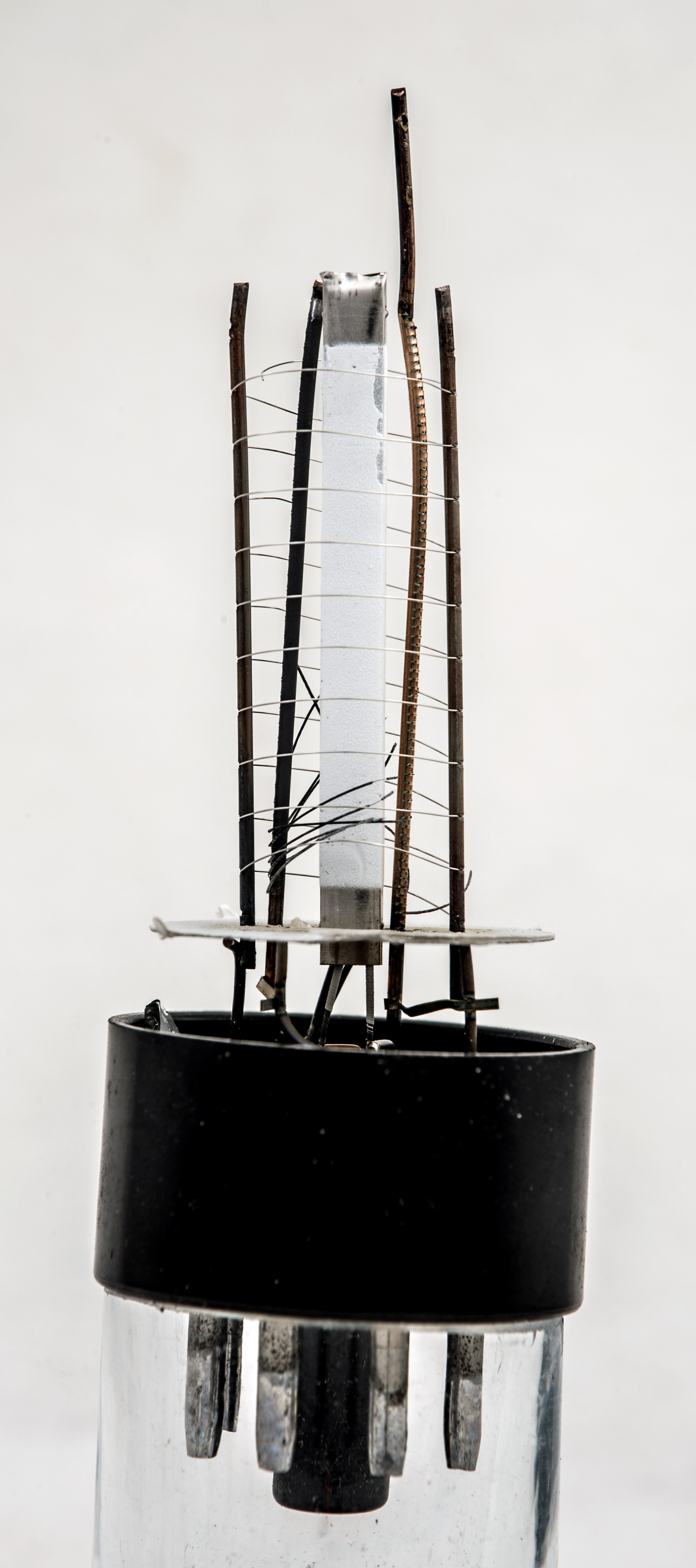
What was left of the inside of the valve.
As the top mica was being removed it was apparent that the grid supports were free to move. The shock when the anode was removed was that the inner grids had disintegrated with no trace of the control grid winding anywhere and just a few pieces of the the screen grid present. The suppressor grid was complete. Clearly a catastrophic event had befallen this EL34.
A closer view. Click to enlarge.
The cathode looks to be mainly complete with some oxide missing at the top. The grid supports had empty slots where the wire should be. The screen grid supports are still bright copper but the control grid support is blackened.
Screen grid support.
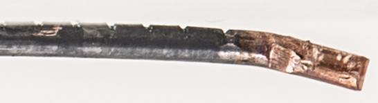
Control grid support.
The inside of this EL34 shows what can happen when things go wrong. It would be interesting to know what caused this level of destruction.
The original valve box.
|