|
Cathode ray experiments at low cost.
This article shows how the amateur may obtain an insight into practical cathode ray working at small expense and with the simplest apparatus.
In its usual form, the cathode ray oscillograph is a rather expensive and somewhat complicated piece of apparatus, almost beyond the reach of the average experimenter. But worth-while results can be obtained (and much useful knowledge can be acquired) with something much less elaborate than the usual 'professional' oscillograph; on the principle that half a loaf is better than no bread, the writer believes that a description of more or less improvised apparatus will be of interest to many readers. With the advent of television, the cathode ray tube becomes almost as important as the valve, and practical knowledge of its technique is of the greatest value.
Miniature Cathode Ray Tube
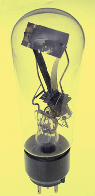 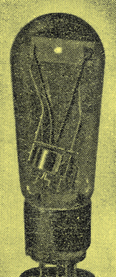
(Left) The Tunograph and (right) the spot on the screen.
The oscillograph to be described may be set up for an outlay of about thirty shillings. The principal item in its construction is the Micromesh Tunograph, which is a miniature cathode ray device designed for use as a tuning indicator in receivers. It was described in The Wireless World for October 13, 1933, and in recent issues of the journal the basic principles of the cathode ray tube have been treated at length.
Readers of this article are assumed to be more or less conversant with these principles, and will realise that in order to make visible a wave-form we need two principal movements of the cathode beam, due to (a) the voltage to be examined and (b) the time base. When the Tunograph is used for its original purpose, as described in the article referred to, an AC voltage, when applied to the deflecting plate, causes a luminous line to appear, and this line obviously corresponds to movement, (a) mentioned above.
Now as the Tunograph lacks a second pair of deflecting plates, the obvious problem is to devise means of deflecting the beam (and consequently the spot) at right angles to movement (a), and the only way of successfully obtaining the time base movement (b) is by magnetic control carried out by means of an external coil.
It has already been pointed out that a cathode stream is capable of being deflected by a magnetic field, and that the beam is deflected at right angles to the field. Various methods of applying this principle suggest themselves, but the most useful in practice is the application of the field produced by a coil fed with AC at 50 Hz in such a way as to produce an elliptical time base. It is necessary at this point to digress for a moment to explain what is meant by this.
If the beam is periodically deflected in such a way that the spot makes a return journey over the same line as it took on the outward journey, then (as waves of the voltage to be examined will be produced by both excursions) confusion of the images will result for two reasons. First, the waves will not necessarily be found at the same place on the two excursions; and secondly, the waves will have been traced in different directions. It is therefore desirable to cause the spot to follow a different path on the two journeys.
This is done by making the time base comprise two movements at right angles in space and at 90°. in time, one being much larger than the other in amplitude. By way of explanation, if these two movements are equal to one another, the result is a circle; if one is larger than the other an ellipse results. How these two movements of the spot are caused will be explained later.
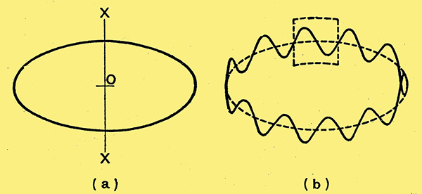
Fig. 1. - The principle of the elliptical time base.
See also: The Bulb of Many Uses.
Assuming that the time base traces out an ellipse as shown in Fig. 1 (a), then if the voltage to be examined is applied to the axis XOX, the effect will be as illustrated in Fig. 1 (b). The appearance of the figures so obtained will be as if the waves had been wrapped round a transparent drum which will appear to be revolving if the frequency of the time base and that of the 'work voltage', as it is called, are not exactly multiples of one another. In the present case the screen of the Tunograph is not large enough to permit of the whole of the ellipse being registered, and only a short portion of it (represented by the dotted rectangle in Fig. 1 (b) is allowed to fall on the screen. This figure shows (approximately to scale) the actual conditions. It must be realised that this time base is not truly linear, but as the screen registers only a small central portion of the ellipse the departure from linearity of this portion is not sufficient to distort the wave-form to any great extent.
Magnetic Time Base Control
The elliptical movement of the spot is obtained by deflecting the beam magnetically in one direction and electrostatically in a direction at right angles (but to a lesser extent), the movements being in quadrature with one another. A coil of wire is thus placed close to the Tunograph so that its axis is at right angles to the cathode stream and parallel to one of the long sides of the screen. It AC is fed to the coil the spot turns into a line across the screen and parallel to its short side. Now the magnetic field is in phase with the current and the current is approximately 90° out of phase with the voltage feeding the coil, so if a portion of this voltage is fed to one of the deflecting plates the spot will have its two movements at right angles.
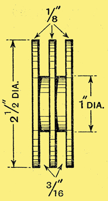
Fig. 4. - Dimensions of deflecting coil former. Each slot may be wound full of No. 32 SWG enamelled wire.
The coil actually used by the writer is similar to a super-regenerative quenching coil, and its construction is shown in Fig. 4. The number of turns of wire is not critical, but, of course, the sense of both sections must be the same. It is necessary to connect in series with the coil a 60 or 100 Watt lamp to limit the flow of current.
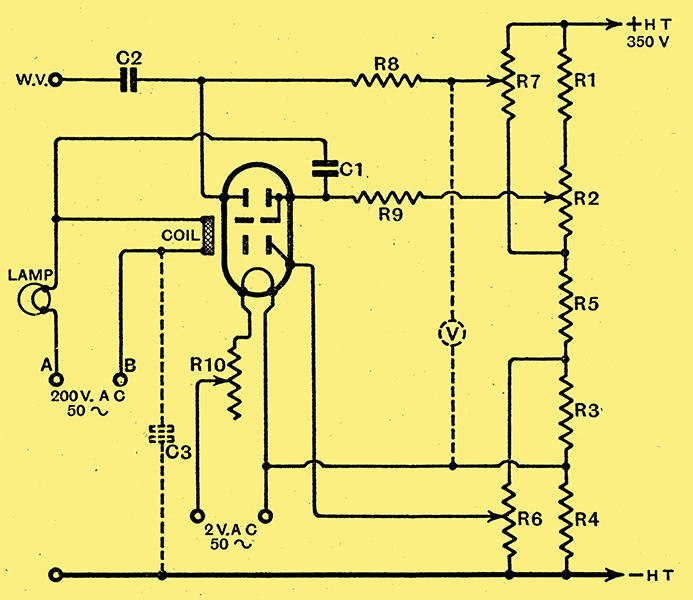
Fig. 2. - Complete circuit diagram of the home-made oscillograph Terminals A and B are mains connections; B should be earthed: Values : R1, 10,000 Ω; R2, 25,000 Ω; R3, R4, 5,000 Ω; R5, 20,000 Ω; R6, R7, 250,000 Ω; R8, R9, 0.5 MΩ; R10, filament rheostat, 4 Ω; C1, C2, 0.001 μF; C3 (if necessary), 0.001 μF or over.
A complete circuit diagram of the apparatus appears in Fig. 2, from which it will be seen that the resistances R1, R2, R3, and R4 constitute a potentiometer across the DC HT supply (in the case of the writer's apparatus, 350 Volts). Provided that a minimum of 200 Volts is available, their values given will be found suitable, though for supplies under 250 Volts R1 and R2 may, with advantage, be replaced by a potentiometer of 30,000 Ω. By way of explanation, it should be added that the potentiometer R2 is used to vary the anode voltage of the Tunograph; R1, R3, R4, and R5 are fixed 1 Watt resistors, while R6 is a 250,000 Ω potentiometer which allows the voltages on the shield to be varied between 25 V positive and 25 V negative with respect to the filament.
With regard to focusing of the spot, the minimum diameter under any working conditions is adjusted by means of R6; the AC potential of the deflecting plate is controlled by R7. Two 0.5 MΩ resistances R8 and R9 serve to isolate the deflecting plates from the circuits supplying their polarising voltage. Out of phase voltage for the time base is fed to one of the deflecting plates through C1, and the bwork-voltage' is fed to the other plates through C2. The procedure in operating is to switch on the DC supply and the filament of the Tunograph. A spot about ⅛ in diameter should appear on the screen when R7 is adjusted, R6 having been set to its maximum. If no spot appears it can be made to do so by holding a permanent magnet near the glass or stroking the glass with it from the base to the top. An alternative method is to disconnect the lead from the shield and apply full DC voltage to it for a few seconds. This produces a kind of haze on the screen, which, 'on' reconnecting the shield lead to its proper terminal, can be brought to a focus by R6.The time base circuit is next switched on, and in all probability the spot will disappear, due to the fact that none of the ellipse appears on the screen, but manipulation of the potentiometer R7 will make visible a line across the screen. It will be found that there are two positions of R7 which will produce lines, these being due to the two sides of the ellipse. Finally, the 'work voltage' to be examined is applied to the terminal WV and the wave-form will appear on the screen.
Uses of the Oscillograph
The particular application to which the writer put his apparatus was an examination of the voltages occurring on the plate of the detector in a super-regenerative receiver. The frequency which was examined was of the order of 10 kHz, and many interesting features have been noticed.
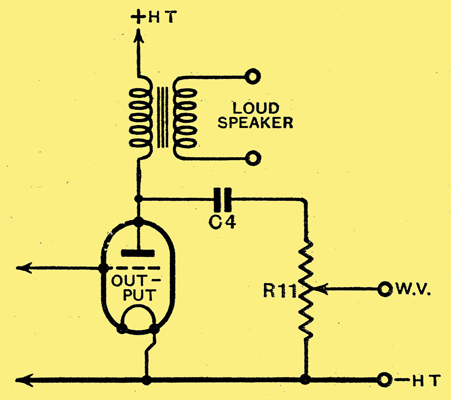
Fig. 3. - Examining the output wave-form Values: R11, 250,000 Ω; C4, 0.01 μF (mica).
No doubt readers will think of other applications, and one which is well worth trying is the examination of the wave-form of the voltages on the plate of an output valve; the circuit for this experiment is shown in Fig. 3. By means of the voltmeter V (in Fig. 2), and by adjusting R7 so as to shift the wave produced across the screen a measurement of the peak voltage can be made.
|