|
A short series of articles on the use of this versatile instrument and some of its auxiliary apparatus A certain amount of fundamental knowledge is assumed, and the articles are intended to give readers a broad idea of cathode ray methods from which they can, with little difficulty, apply the principles to their own needs.
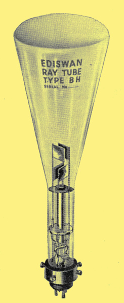 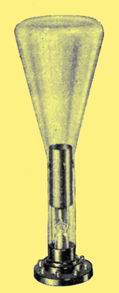 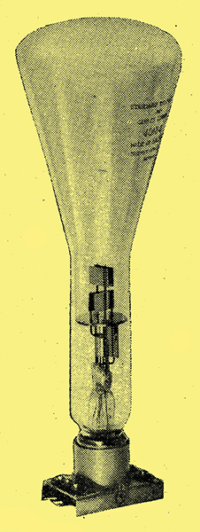
Left - An Ediswan CRT. Centre - a Cossor CRT in-holder. Right - Standard Telephones and Cables CRT.
The principles of the cathode ray tube are now fairly familiar to most readers, and its use in a vast field of research and experiment has been the subject of much technical writing. Its potentialities in television further make it an object of great current interest, and it is thought that a simple explanation of the tube and of some of its uses may be of value. An appreciation of the operation of the device will undoubtedly be of help in following the various television systems, besides being of assistance to experimentally minded readers who may wish to use this remarkable diagnostic tool in their experiments.
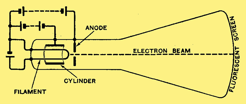
Fig. 1. - Production of the electron beam in a cathode ray tube.
Briefly, the tube itself consists of a three-electrode device, the purpose of which is to shoot a beam of electrons along the length of the containing bulb. A typical construction is shown diagrammatically in Fig. 1, where the filament, shown in the form of a simple U, is heated by current (from a battery or other source), while a high-tension voltage is applied between it and the anode. The latter electrode is usually in the form of a disc with a central hole. Electrons are liberated from the filament and drawn towards the anode, where some of them - indeed, a great many of them - arrive with sufficient velocity to shoot through the anode aperture. By attention to the length of the bulb and by adjustment of the degree of evacuation (and also by the use of a minute quantity of some of the other gases), it is possible to produce an ionisation effect along the bulb which keeps the electrons in a fine beam or jet. This process can, however, be greatly assisted by surrounding the filament by a 'Wehnelt' cylinder, as shown in Fig. 1, and making the cylinder negative to the filament. This negative charge immediately exercises a constricting effect on the beam before it reaches the anode, thus making it easier to keep the beam in a fine pencil after passing through the anode aperture.
The electron beam is then projected along the bulb until it meets the flattened end, the inside of which is coated with a material that glows or fluoresces under the influence of the electron impact, thereby producing a bright spot of light. Several different fluorescent materials are in current use for different colours of fluorescence. The most active visual material is zinc-silicate or Willemite, which glows a bright yellow-green, to which the eye is most responsive. For photographic purposes, calcium tungstate, which glows a bright blue colour, appears to be the best material. Cadmium tungstate can also be used, and mixtures of these substances can be made to give a fluorescence fairly well suited for joint visual and photographic requirements, as is often required in experimental work.
The process of bringing the beam to a sharp point where it impinges on the fluorescent screen is usually described as focusing it. In practice, once the tube is made and its vacuum fixed by the maker, the process of focusing is done jointly by adjusting the filament current and the negative voltage on the cylinder. The filament, cylinder, and anode system is frequently called the electron gun, from its function in shooting electrons along the tube.
The description and illustration given are true of the general type of soft vacuum tube used for measurement and experimental purposes. This tube has certain inherent defects which render it less suitable for television, for which purpose a hard or highly evacuated tube is desirable. The focusing process is then rather different, since there is no help from ionisation within the tube, and focus is controlled in a number of different ways, mostly by auxiliary electrodes, additional to those described. These methods need not, indeed, cannot, be discussed in a general article such as this.
The purpose of the electron beam is to serve as an indicating device for whatever purpose we want to use it. Besides the gun system illustrated, therefore, the tube usually contains some means of deflecting the beam. These will be considered later, and, before we proceed to consider even the details of the electron gun circuits, it will be well to digress and review some of the actual uses of the tube.
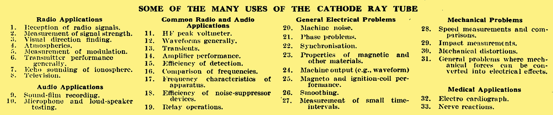
Applications of the Tube
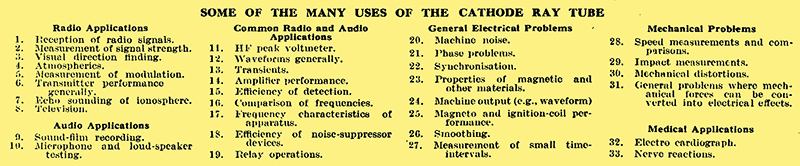
These uses are many and varied. The list given in the table is extensive and typical, but does not claim to be exhaustive.
The list looks very formidable, but the applications can be classified into a few simple essential forms. These are (a) the delineation of phenomena against time, (b) the comparison of voltages for amplitude, phase or frequency, (c) the general plotting of cause and effect (e.g. by the production of voltages proportional to those qualities). For example, the essential form of (a) covers the applications listed in 1, 4, 6, 7, 8, 9, I2, I3, I5, I8, 20, 24, 25, 26, 27, 28, 32, 33; (b) covers the applications 2, 3, 14, 15, 16, 21, 22; while (c) covers the applications 5, 6, 10, 17, 23, 28, 29, 30, 31.
It is, perhaps, well to crystallise these essential forms at an early stage, since knowledge of them is of the greatest advantage in assisting the intending user to devise schemes to suit his particular requirements. It may also be of help to him in interpreting results when he has got them, since, in some cases at least, lack of clear thinking may prevent him appreciating all the information that is to be obtained from his observations. It will be noticed that certain applications fall into two of the three categories, according to the exact method used.
A previous article on the subject (in The Wireless World of April 6th, 1934) illustrated two very important accessories in the use of the tube, viz., a thigh-tension supply unit and a linear time-base unit. The former provides economically the high-voltage and low-current output necessary for the operation of the tube. The second is a very useful accessory, in some form or other, in most of the applications mentioned in (a). That illustrated in the previous article is one of the most flexible single units available, since it can be used over a wide range of frequencies and a wide range of voltage swings (i.e., amplitude on the tube screen), and can also be synchronised or locked to a recurrent phenomenon such as a steady waveform.
The cost of these items may, however, be somewhat terrifying to the amateur experimenter, and it is the intention of this article to illustrate and describe some inexpensive methods of constructing devices which, although perhaps less elegant than those formerly illustrated, are quite serviceable for many purposes.
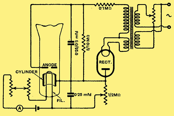
Fig. 2. - 'Electron Gun' circuit of cathode ray tube.
The essential circuits of the electron gun, or electron-beam-producing device, shown in Fig. 1, are given in Fig. 2 in association with the simplest possible type of HT supply unit. Although reference was made in the previous article to the use of a unit Supplying up to 3,000 Volts, with modern oscillograph tubes it is rare that more than 1,000 Volts are required except for the most rapid photographic applications and for television. For visual working of all kinds (except television) and with a suitable screen material giving the greenish fluorescence to which the eye is most responsive, 1,000 Volts are usually sufficient.
The tube filament can be heated by AC or by battery, the latter being illustrated in Fig. 2. An ammeter should always be used in this circuit, and the filament current worked up gradually to the value stated by the maker. If this is not known, it should be worked up gradually to the lowest value necessary for focus, as although modern cathodes are fairly robust it is not wise to try them too severely.
Improvised HT Supply Unit
On account of the very small anode currents used, the HT supply unit can be of the simplest type, e.g., a half-wave rectifier with very simple smoothing. Again, on account of the low currents, the transformer can be a small one, the only qualification being that of good insulation between its windings. A transformer of ratio 3 or 4 to 1 can be used for the HT side (provided its insulation is good enough) to give a smoothed DC output up to about 1,000 Volts. An old audio transformer can sometimes have its insulation improved by simple means and used for this purpose. The transformer heating the filament of the half-wave rectifier should also have good insulation between windings.
The rectifier itself, as mentioned in the previous article quoted, is not critical. The volt-drop across it in the conducting direction is very small, but in the non-conducting direction it has practically the full peak-voltage of the negative half-wave, and its base and socket should be of good insulation for this reason. Cossor make a special valve, SU2130, but an old triode (with grid and anode strapped together) is a good substitute, especially for operation at 1,000 Volts or so. Even with about 1,000 Volts as a working value, control of the HT output is very desirable so that the tube can always be operated at a lower voltage if circumstances permit (as frequently they do). The heavy-duty potentiometer across the primary of the HT transformer does this very well. The 0.1MΩ series resistance serves as a general protection, that of 5 to 10MΩ across the HT capacitor acts chiefly as a discharging load when the tube is switched off.
The variable resistance of 1 to 2MΩ between cathode and cylinder serves the familiar wireless purpose of free grid bias to adjust the cylinder to the correct negative potential for good focus (in conjunction with the filament current). A pilot lamp is a useful refinement if a suitable LT transformer winding is available, but a small neon lamp across the primary can also be used. Most tubes can now operate with AC on the cathode, and for this purpose another LT transformer might replace the battery shown in Fig. 2. Two rheostats giving a rough and fine filament control are desirable with either AC or battery, 4Ω for the rough and 1Ω for the fine being typical values. The beginner setting up a cathode ray tube and its accessories will mostly be influenced by the material he has available. The use of an ammeter in the filament circuit has already been emphasised, and if an ammeter has to be bought for the purpose a moving-iron instrument is recommended so that it can be used for AC or DC. High-tension volts can only be measured by an electrostatic instrument on account of the relatively large load imposed even by a high-resistance, moving-coil instrument, so we must generally take them on trust.
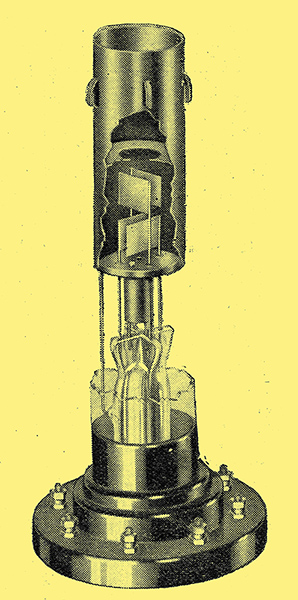
A cut-away illustration showing the mounting of two pairs of deflecting plates inside the Cossor tube.
Having found a way of producing our electron beam we must now consider the means of using it as an indicating device. The beam is usually controlled by the well-known deflecting plate system, of which the construction can be seen in the 'ghost' photograph above and their operation in Fig, 3. One pair of plates (VP of Fig. 3) permits the beam to be [deflected up and down, while the other pair (HP) permits it to be moved horizontally.
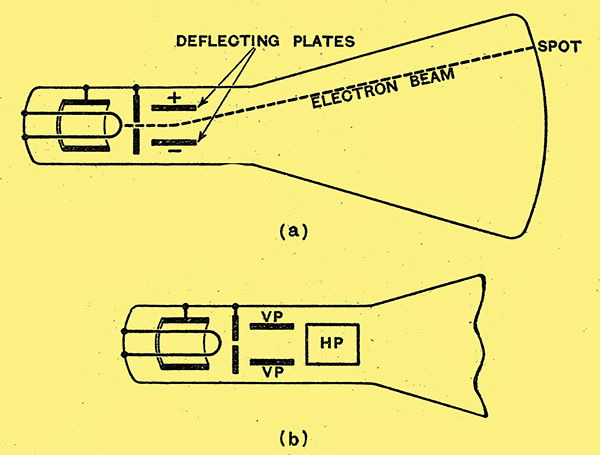
Fig. 3. - Deflection of electron beam by plates within the tube : (a) one pair of plates deflecting beam vertically; two pairs of plates, VP for vertical deflection, and HP for horizontal deflection.
In skeleton diagrams these plates are usually illustrated as shown in Fig. 4, which gives the impression of the two pairs, one-moving the spot vertically and the other horizontally. The central dot in Fig. 4 can be regarded as representing the electron beam or it can be regarded as representing the anode from which the beam emerges. It is essential to have a conducting path between each deflecting plate and the anode, otherwise charges build up on the plates and spuriously deflect the spot. It is now common practice to bring all four deflecting plates out to separate terminals, and this matter of ensuring a conducting path from each plate to the anode must therefore be borne in mind.
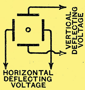
Fig. 4. - Skeleton circuit of deflecting system.
Several different ways of doing this and of connecting the plates to external circuits are shown in Fig; 5. For example, Fig. 5 (a) shows one of the simplest types of connection. In normal operation the anode of the tube is earthed and this circuit shows one plate of each pair directly connected to it, while the other is joined to an output circuit. This assumes, of course, that this circuit has one side earthed or earthy. It it has not, but has or can have a centre earth, then the scheme of Fig. 5 (b) is applicable, this amounting to push-pull connection. It the output cannot have a centre earth directly connected, the equivalent can usually be obtained by means of a high resistance across it, centre earthed.The respective uses of these two methods are dictated entirely by the type of output circuit to which the tube is to be joined. Fig. 5 (c) illustrates a very useful case in which the tube is applied to examine, say, the AC component in a circuit which also carries DC. Since the tube responds alike to AC-and DC it will be seen that the (DC component will have the effect of pushing the spot to a new position on the screen (or off it if the DC is large). The DC can be eliminated, but the AC passed on to the tube by the resistance-capacity coupling system shown in Fig 5 (c), again assuming an output circuit with one side earthy. If this is not the case the double capacitor system of Fig. 5 (d) can be used, being again the equivalent of a (resistance-capacity) push-pull circuit. In all the cases of Fig. 5 only one pair of deflecting plates has been shown completely connected in order to simplify things, but it will be realised that exactly similar reasoning is applied to the other pair according to the actual type of circuit with which it is used.
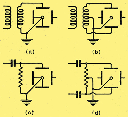
Fig. 5. - Different methods of joining up the deflecting plates.
It will be seen that all the arrangements shown fulfil the condition of having a conducting path from peach plate to anode, but it should be mentioned that this path can be quite a high resistance. For example, in Fig. 5 and (d) the resistance across the plates can be 1 or 2MΩ, with capacitors up to 1 μF according to the frequency to be passed. It will also be seen that the push-pull connections of Fig. 5 and (d) could be applied to one pair of plates, while the one-side-earthed connections could be applied to the other pair if this is most convenient in the conditions of use.
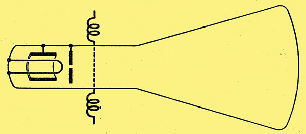
Fig. 6. - Deflection of electron beam by current-carrying coils outside the tube.
Besides deflection by the plates inside the tube the beam can also be deflected by means of the magnetic field of a coil or coils outside the tube. This is possible because the; beam, being composed of moving electrons, is the equivalent of a current-carrying wire, but without inertia, and can therefore be influenced by a magnetic field in just the same way as the coil in our moving-coil instruments. The use of a feeble permanent-magnet is, indeed, a well known means of moving the spot about to any desired position on the screen. For deflection by means of current-carrying coils it is usual to employ two coils in series for each dimension of deflection, one pair for a single dimension of deflection being shown diagrammatically in Fig. 6. An important distinction to remember, however, in the case of coil deflection is that the beam is deflected at right angles to the magnetic field. Thus, in Fig. 6 the magnetic field is applied vertically and the spot moves horizontally. For most practical purposes electric deflections by the plates is the more useful, but there still sexist cases where ability to use magnetic coil-deflection is very valuable.
Before we referred to the use of a time base, and it will be remembered, from the list of applications given, that many of these reduce to the measurement of some quantity against time.
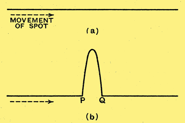
Fig. 7. - Illustrating the use of a time base.
In practice, therefore, the use of a time base voltage becomes the simple one of making the spot move, say, from left to right in some,known period of time, and observing the phenomena that, occur during that time. For example, in Fig. 7, if the spot is moved from left to right its transit will be represented by the line shown in (a). If, at some point, P in this transit, the spot suddenly receives a deflection in the vertical direction, then, since it is capable of moving in both directions, it will do so, returning to its zero line at the end of the impulse and completing its time stroke from Q onwards, as shown in (b). If the whole process is sufficiently slow to be followed by the eye this can, of course, be seen, but in practice. it is much more usual to want the cathode ray tube for speeds that the eye cannot ordinarily follow. Suppose, for example, that the process of Fig. 7 is repeated, say, 50 times a second, and that the vertical kink always lands in the same place along the time stroke. The result on the fluorescent screen will then be a steady picture. (Fig. 7, (b)), of the wave form of the transient phenomenon.
An excellent time base circuit was illustrated before, but; before dealing further with practical, circuits for obtaining a time-base, it will be well to consider the types of voltage that we can apply to the horizontal deflection plates for the purpose. From what has been said above it will be realised that the voltage used should be a repeated or recurrent one, and a voltage conforming to this description is available (in most places where the cathode ray tube is likely to be used) in the form of the 50 Hz mains.
Sine-Wave and Saw-tooth Voltages
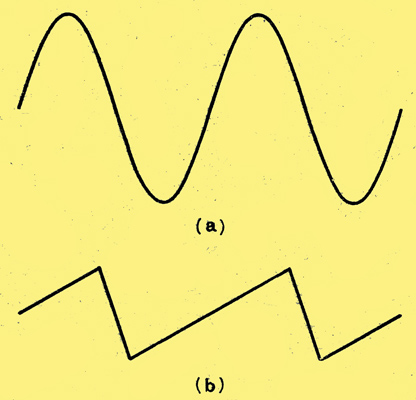
Fig. 8. - Variation of sinusoidal voltage (a) and of saw-tooth voltage (b).
The wave-form of an ordinary alternating voltage is of the sinusoidal form shown in Fig. 8 (a). But there is another kind of wave-form that we can have for use with the cathode-ray tube and which will be increasingly referred to in connection with the application of the tube to television. It is one which, if applied to the plates of the tube, causes the spot to move slowly and uniformly, say, from left to right with an abrupt return from right to left which lasts only a small fraction of the time taken to travel from left to right. If we plot such a voltage against time the wave-form is of the type shown in Fig. 8 (b), and it is usually described (from its shape) as a saw-tooth voltage.
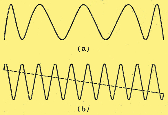
Fig. 9. Difference of wave-forms shown on a sinusoidal (a) and saw-tooth (b) time base.
The essential difference in the behaviour of a sinusoidal and a saw-tooth voltage when used as a time base for a cathode-ray tube is shown in Fig. 9. In the upper picture (a) we have a sinusoidal voltage of 50 Hz applied to the horizontal plates and one of ten times this frequency, that is, 500 Hz, applied to the vertical. Thus, is moving back and forward once the spot moves up and down ten times, but on its backward journey retraces the same path as in its forward journey, so that only five cycles are visible. Moreover, the cycles do not appear to be of equal length because the spot is not moving uniformly back and forward, but is moving more rapidly during the middle part of its stroke than at the end. On the other hand, Fig. 9 (b) shows a saw-tooth time base of the same frequency and the 500 Hz again applied vertically. In this case, since the spot is moving uniformly from left to right, all the cycles of the 500 Hz voltage now appear of equal length, and all ten are shown, except for the very small part of one cycle which is lost in the abrupt return journey from right to left.
From this it will be apparent that a saw-tooth source is much preferable for time base purposes. Despite this, however, a very great deal of use can be made of the 50 Hz mains in-many waveform applications, and the beginner who desires to incur the minimum of expense in his first set-up will be well advised to start off with this simple time base, since it costs so little. There is only one point of care to be noted, that is, that it is always desirable to have a transformer between the mains and the deflecting plates. One side of the mains is normally earthed and there is a liability to get this mixed with the earthy side the deflector plates, with disastrous results. Additionally, with low tube voltages the mains will usually deflect the spot too much. Both difficulties can be obviated by using a small transformer between the mains and the horizontal plates. This can be 1:1 or actually step-down, and need only be very small in size since the load is negligibly small. An output transformer or a suitable inter-valve transformer, working backwards as a step-down, is quite suitable, according to the deflection desired.
Elliptical Time Base
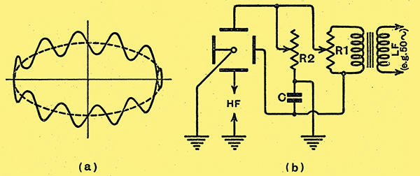
Fig. 10. - Sinusoidal voltage shown on an elliptical time base, and (b) circuits for obtaining this timebase.
Even with a sinusoidal time base, although the whole horizontal stroke is not uniform, the middle portion of it is practically so and can be used for accurate time measurements. This can be seen, in Fig. 9 (a). The difficulty of the spot traversing the same path backwards (referred to in connection with Fig. 9 (a)) can be avoided in a very. simple way. This is, in fact; not to let it travel the same path backwards, but to make the time base move elliptically as shown in the dotted ellipse of Fig. 10 (a). The circuit for producing an elliptical time base is shown diagrammatically in 10 (b).
The principle of the method is that if we apply an alternating voltage to a capacity and resistance in series the voltage-drops across the capacitor and across the resistance differ in phase by 90°. If the resistance is exactly equal to the impedance of the capacitor they are of equal value but differ in phase by the amount stated; if the resistance is less than the impedance of the capacitor the voltage across the resistance is less in value, but the phase difference remains as stated. This is simple AC theory. Thus in Fig. 10 (b) if the capacitor C is 0. μF it will have an impedance of just over 30 kΩ for 50 Hz. If the variable resistance R2 has a value up to 30 kΩ the drop across C and across R2 can be made anything up to equal value, with a constant 90° phase difference. it If the plates of the tube be connected as shown the presence of the phase-difference sends the spot round in an ellipse as shown dotted in Fig. 10 (a), which can be widened up to a circle when R2 = 30 kΩ. For time base purposes a 2:1 ellipse (as shown), or even narrower, is quite suitable, and R2 is adjusted accordingly; R1 simply serves as a control of the whole size of the ellipse, and its value should be low compared with the 40 kΩ or so of the series capacitor and resistance. The transformer between R1 and the mains is absolutely essential, on account ofb the earth midway between C and R2, and it should be big enough to deliver the requisite maximum voltage across R1 with a resistance of about 5,000 ω. It will be seen that the 50 Hz frequency uses only one plate of the vertical pair, and the 500 Hz frequency (or other source under examination) is joined between the other plate and the earthy anode. Switching on.the 500 Hz source then gives a pattern such as that illustrated in Fig. 10 (a). This should be compared with Fig. 9 (a). It will be seen that in both the middle of the time base strokes are very uniform and quite useful for time measurements or waveform examination, while Fig. 10 (a) shows the back and forward journeys separately, so that if the voltage under test differs on these journeys the differences are clearly shown.
The cases given illustrate not very high ratios (only 10 to 1) between the frequency of the time base and that of the voltage which is being examined on the vertical plates. The amount of opening up of the waveform depends, of course, on the frequency applied to the vertical plates. If this is at all high, a moderate length of 50 Hz horizontal time base deflection gives insufficient opening. This difficulty can be overcome by using a much larger 50 Hz voltage; so that the ends of the horizontal line or ellipse (which are in any case of little use) are right off the screen. The middle portion of the sinusoidal time base will then be spread out and the vertical deflections well opened. Valuable information can often be obtained by such a simple time base, and the beginner would be well advised to acquire experience with the tube working on this inexpensive time-base source before launching out with more costly equipment. But the precaution of a transformer between tube and mains is most important.
There is little doubt, however, many users will soon wish to use a saw-tooth voltage giving a linear time base stroke. Fortunately there are quite a number of simple and inexpensive circuits for this purpose, some of which can readily be made up from components most experimenters are likely to have available.
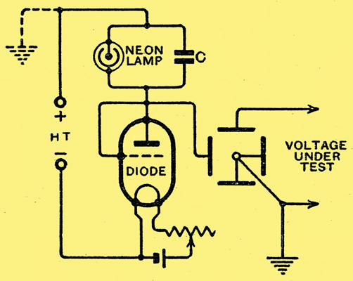
Fig. 11. - A saw-tooth time base circuit depending on the periodic charge and discharge of a capacitor in association with a neon lamp.
One of the earliest of these used with a cathode ray tube (and still quite a useful one) is illustrated in Fig. 11. It utilises the arrangement known as a ticking neon lamp circuit. The components are a neon lamp, a capacitor C (for which 0.1 μF is a useful general value) and a diode which can be an old bright emitter valve with its grid and anode connected together. A bright emitter or thoriated filament is essential; an oxide coated valve is useless. When the HT voltage is applied a charge builds up across the capacitor at a steady rate of charging current due to the action of the saturated diode. This goes on until the capacitor voltage reaches a value sufficient to trigger off the neon lamp. The capacitor is then immediately discharged, or rather, its charge is reduced to a value which no longer keeps the neon lamp excited.The capacitor charge proceeds to build up to striking voltage again, and so on, at a rate depending on the capacity of the capacitor and the brightness of the diode, which can be smoothly varied over fair limits to get an appropriate rate. For greater variation different sizes of capacitor can, of course, be used. The use of the diode is to make the long part of the saw tooth (of Fig. 8 (11)) straight, instead of exponentially curved as it would be if a simple resistance were used as the charging impedance in series with the capacitor.
If the tube is being operated off a low HT voltage (300 or 400 Volts), the same source can be used for the time base and the particular connections of Fig. 11 are arranged to allow this.
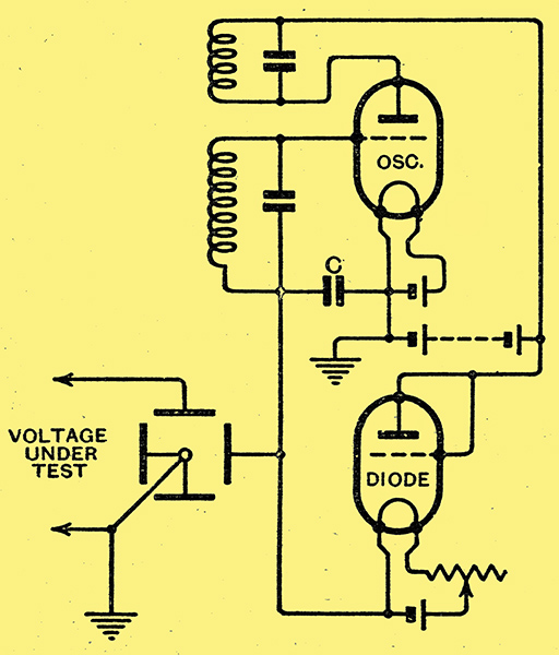
Fig. 12. - A 'squegger' oscillator as a generator of a saw-tooth waveform.
Another simple saw-tooth circuit which is an old time base favourite is shown in Fig. 12. It is a squegger or ticking grid circuit, consisting of an oscillator with a high impedance between grid and filament. This consists of the capacitor C and the diode as a grid leak. The oscillator coils should be such as to give an ordinary coupled-circuit oscillator system of 150 to 300 metres, and can be tuned by small capacitors to give the strongest oscillation possible. After a few cycles of oscillation the grid goes negative and oscillations stop. The capacitor then discharges through the diode giving the slow time stroke of the saw tooth. When the capacitor discharges the oscillations begin again and quickly recharge the capacitor, giving the sharp back stroke. The rate, as before, depends on the capacitor and the brightness of the diode, which is again used in this case to give a straight line to the saw-tooth. The disadvantage of this circuit is that, since radio frequency is generated, it tends to 'speak' into other wireless circuits, but this can be minimised if not completely , suppressed by screening. It is not desirable to use a common HT for tube and time base, but the currents taken are small and a simple eliminator of conventional type can be used.
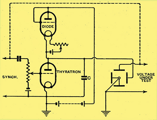
Fig. 13. - A Thyratron time base circuit.
A newer and very useful saw-tooth circuit is shown in Fig. 13. It is rather similar in operation to the neon lamp circuit of Fig. 11, but uses a thyratron as the discharging device. The ordinary type of mercury vapour triode or thyratron is suitable for time base frequencies up to 1,000 Hz or so, but beyond that a neon thyratron is preferable and is now made by several firms.
A particularly valuable feature of this circuit is the ease with which it can be locked or synchronised with the voltage applied to the vertical plates. When using a time base for examination of a higher frequency source (such as an oscillator) a steady pattern of the type shown in Fig. 9 is obtained only when the vertical frequency is very exactly a multiple of the frequency of the time base. If this is not the case the pattern drifts at a rate depending on the difference from such a multiple ratio. If we move one control very slowly from one multiple ratio to the next the design on the screen moves from a simple pattern through a series of patterns of varying complexity to the next exact ratio.
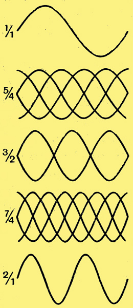
Fig. 14. - Patterns on screen with simple fractional relations between linear time base and vertical voltage.
An indication of some of the simpler cases that can be seen is given in Fig. 14, when we start with one cycle of the vertical to one sweep of the time base and then proceed to increase the frequency of the vertical until it is 2:1. The examples given are only a few and certainly the simplest that are to be seen, and all are very difficult to hold steady.
In practice, however,. we very rarely do want to hold such patterns as the intermediate values, but rather of the exact multiples such as 1:1, 2:1 or the 10:1 of Fig. 9 This is where the ability to lock comes in very useful. This can be done by feeding into the grid of the thyratron a. small fraction of the voltage being applied to the vertical plates of the tube, as shown by the synchronising terminals at the left of Fig. 13. With a high resistance potentiometer (1 or 2MΩ) the load of this circuit on the output of the circuit under test is negligibly small, and adjustment of the value joined to the grid causes the pattern to change from a slowly drifting one and to assume a steady condition as already shown in Fig. 9 (b). It will be seen that the connection indicated is actually that shown by the dotted line in Fig. 13.
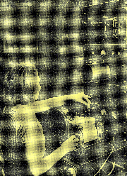
Resonance curves made visible: the cathode ray tube as an aid to trimming ganged circuits.
In all the three saw-tooth circuits shown it will be seen that the diode is at a high negative potential to earth, and it and its battery should therefore be well insulated. Instead of a diode a screened grid or pentode valve can be used, taking advantage of the length of approximately flat Ia/Va characteristic which both valves give. The speed is then varied by controlling the screen voltage by means of a potentiometer, or additionally by capacitor steps as already discussed.
Lastly, we must deal with what are most conveniently called shift circuits. The saw-tooth circuits shown, and most others in practical use, have some DC component in their output which deflects the time-base to one side of the screen. As a rough and readybmeasure it can, as already stated, be restored by a magnet, or more smoothly and controllably by extra coils carrying a direct current whose value is varied by means of a rheostat. A very neat alternative is to use DC voltages applied between one plate (of each pair) and anode, While the other plate is in use for alternating deflection. This is only possible when all four deflecting plates are available for connection, that is to say, when they have no common connections inside the tube.
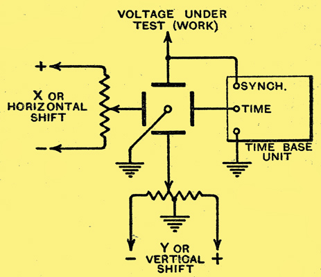
Fig. 15. - Principle of shift circuits.
The necessary shift can be obtained by means of fixed voltages between plate and anode, joined in the sense to give the displacements necessary. On the other hand, it is frequently useful to be able to move the pattern smoothly over the screen, and typical methods of doing this are illustrated in Fig. 15.The potentiometer used can be of quite-high resistance, being thus very light on batteryb consumption. The arrangement shown for the horizontal deflection is for one-way movement only, according to the sense of the battery connection, which can be reversed if desired. The shift on the vertical deflection allows for. smooth movement up or down, but, of course, either arrangement can be used on either deflection according to needs. The diagram also shows the schematic arrangement of locking or synchronising the work and time base, after the manner already discussed in connection with Fig. 13 in order to get a steady pattern.
Throughout these articles the attempt has constantly been to indicate general methods and principles which any experimenter can apply with the minimum of difficulty to his own requirements. In particular, it is hoped that they may help him to cut his coat according to his cloth, and, fortunately, it is not so difficult as it is in 'gents' tailoring to add to the coat as one gets more cloth
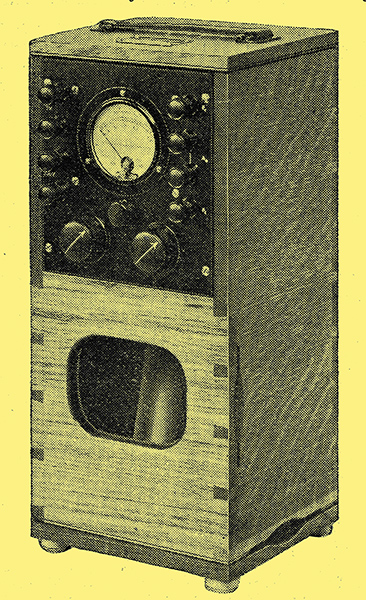
An oscillograph unit from Standard Telephones and Cables, Ltd.
|