|
How to build a DC to AC Converter.
The author describes the construction of a purely static device, without any moving parts, for converting DC current to AC for operating receivers, amplifiers, or other purposes. By choosing thyratron valves and a power transformer of appropriate types, AC outputs of either 100 or 400 Watts may be obtained.
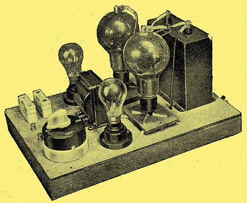
A 400 Watt inverter using lamp resistances. Layout of components a matter of practically no importance.
The process of rectification of alternating current is now well understood, and apparatus of any desired output capacity is available. With regard to the opposite process, methods of converting DC power into AC have been devised using motor-alternators, arc generators, vibrating reeds in conjunction with induction coils, and, more recently, gas triodes or thyratron tubes. The properties of the last-named are used in the inverter here described, which is designed for a full-load output of 100 or 400 Watts according to the tubes employed. The apparatus is entirely static, and shows advantages of high efficiency and low initial cost.
A previous article [★] See extras index has outlined some of the most important features of these tubes, which are essentially triodes containing a small quantity of residual gas, generally argon or mercury vapour. In operation, the electrons passing from cathode to anode ionise the atoms of residual gas and form other ions by collision. The positive ions fall slowly on to the cathode, neutralising the negative space-charge near it. This space-charge accounts for the high internal resistance of hard valves and involves the dissipation of large amounts of energy if an attempt is made to pass a large space current. This energy appears as heat at the anode, and limits the power-handling capacity of the valve.
The voltage drop across the thyratron tube is reduced by the positive ion sheath to about 20 Volts, so that for a given anode dissipation large currents may be passed. Several other special characteristics follow as a consequence of the residual gas filling. The chief of these are that the voltage drop between anode and cathode must not exceed 15 to 22 Volts, and the filament or heater voltage must be low (usually 5 Volts or less) in order to avoid cathode disintegration by positive ion bombardment. Most important is the modification of the control action of the grid. If this is maintained negative no anode current passes until the voltage reaches a critical value, Then a discharge passes, which is limited only by the external circuit resistance. The grid ceases to exercise further control owing to the formation round it of a positive ion sheath, and current can only be stopped by switching, or by temporarily reducing the anode voltage to a, value in the neighbourhood of 15 Volts. This may be done by switching a capacitor across anode to filament, after which, if the grid is sufficiently negative, the discharge will not start again. The ratio of anode voltage to the negative grids voltage which will just prevent the flow of space current is known as the control ratio of the tube, and corresponds to the amplification factor of a hard valve.

Fig. 1. - Illustrating the principles of operation of the thyratron inverter.
Work on gas-filled tubes has led to the production of valves capable of passing space currents of the order of the Ampere. By passing this current through the primary of a transformer, and interrupting or reversing it, an AC output is obtained. In practice, this operation is best performed by two-tubes. The circuit of Fig. 1 shows what appears to be a conventional push-pull amplifier, with the addition of a capacitor joining the anodes of the valves. An input AC is applied to the grid transformer. Suppose the grid of tube A swings positive, While B swings negative by the same amount. The first tube passes anode current from the supply, which cannot subsequently be stopped by the control grid. At the end of a half-cycle of the AC the grid of B becomes positive, and that of A negative, while the action of the output transformer has charged up the capacitor C during the time the valve A passed current. Immediately tube B commences to conduct, a the charge on this capacitor has the effect of driving the anode of A negative, which stops its discharge. This does not start again, as the grid is now negative, and remains so until the next cycle commences. The action is repeated, and each pulse of current through the, half-primary of the output transformer behaves like a half-cycle of an ordinary AC supply. The choke coil shown serves to improve the commutation of current from valve to valve.
Automatic Grid Control
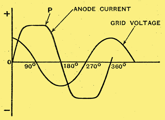
Fig. 2. - Phase relationship between grid voltage and anode current in a self-exciting inverter.
The objection to the simple inverter shown is the need for a control AC, and means have been devised for effecting the commutation by utilising the output AC. The method may be seen from the curves shown in Fig, 2, which represents one complete cycle. For the first quarter period the grid voltage is shown positive, and the associated tube passes current as shown. At the point P, the grid of the second tube has swung sufficiently positive to trigger the discharge, and the action of the anode capacitor stops the current through the first tube, which does not fire again until the grid becomes sufficiently positive, To effect the desired commutation of current, the grid voltage must lead the anode current, which suggests the further point that in the use of this form of inverter on an inductive load commutation will be difficult. A lagging power factor may be corrected by the use of capacitors across the load. Those familiar with AC working will see that to obtain the phase relations between anode current and grid voltage shown on the graphs, it is sufficient to design a phase correcting network to give a lead of approximately 90°.
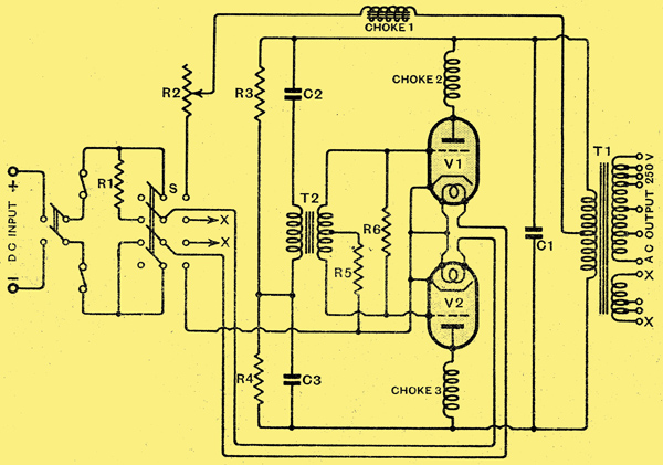
Fig. 3. - Compete circuit diagram of the inverter. R1, R2, see text; R3, R4 5,000 Ω, 20 Watts, R5 5,000 Ω, 5 Watts, R6, 10,000 Ω 5 Watts, C1, 4 μF C2, C3, 1 μF (all 1,500 Volts working), V1, V2, thyratron tubes.
Fig. - 3 gives the full circuit diagram, with values of components. many of them are standard radio products, but the four-pole change-over switch S, the power resistances R1 and R2, the main choke No.1, and the transformer T1 may not readily be obtainable. The function of the switch is to run the valve heaters from the mains through the voltage dropping resistance R1 until the cathodes are sufficiently heated for conduction to commence. In the running position, this resistance is cut out and the heaters worked from a winding marked XX on the main transformer. During preliminary adjustments it is best to run them from a car battery, tapping off the voltage required.
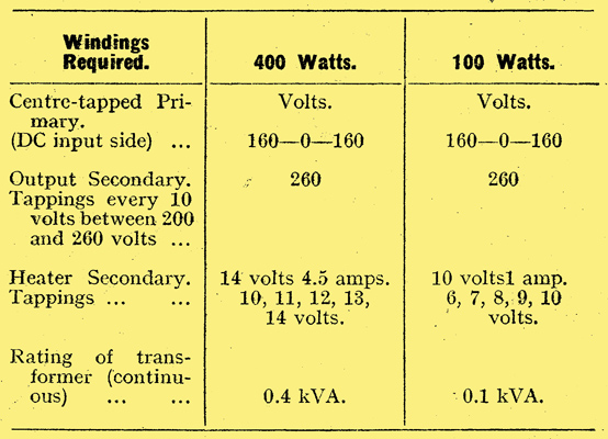
The values of the resistances R1, R2 depend on the heater voltage and current of the tubes, and on the maximum permissible anode current. The requirements of the recommended tubes are indicated in the table.
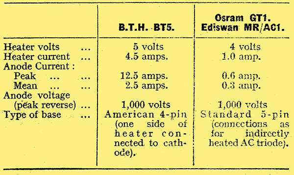
Thyratron characteristics.
The heater of the BT5 requires 5 Volts 4.5 A, or for the two in series, 10 Volts 4.5 A. The smaller tubes, MR/AC1 ,and GT1, each, require 4 Volts 1 A, or in series, 8 Volts 1 A. The resistances required may be calculated by subtracting the total filament voltage from the mains voltage and dividing by the heater current. For the BT5, assuming 250 Volt mains, the required resistance is (250 - 10)/4.5, or almost 53 Ω. This resistance might be made from a 1 kW 250 Volt heating element or fire bar, the wire being cautiously unwound until, on test, a current of 4.5 Amperes is passed.
If the smaller tubes are used, the resistance is (250 - 8)/1, or 242 Ω. A bank of lamps totalling 240 Watts, could be employed here, the exact current being measured and adjusted to the correct figure by trying lamps of different rating. The value of the resistance R2 is not critical, and may be 60 Ω maximum for the BT5 or 400 Ω for the GT1 or MR/AC1.
The resistance can be used, if desired, to give a control over the output voltage, but must then be capable of carrying -continuously the full-load anode current. The switch S may conveniently consist of two double-pole change-over switches connected by a coupling bar.bThe chokes Nos. 2 and 3 are connected as close to the anodes as possible, and serve to keep radio frequency disturbances from the output side. They consist of a few hundred turns of wire heavy enough to carry the anode current, and may be wound on tubular formers, or in the form of taped slab coils. Two similar chokes may be placed in the DC lines, and when these precautions are taken it is possible to operate a sensitive receiver from the output, or from the DC mains, with no interference except that radiated direct from the apparatus. This can be completely suppressed by screening the whole apparatus or by placing it in a metal box. Readers may be reminded that a good earth minimises the risk of any interference, which in this case is almost entirely confined to the Long Waveband. The anode chokes also serve to prevent cathode disintegration by the heavy instantaneous currents resulting from the discharge of the anode capacitor when each tube fires. This is a well-known cause of premature failure of thyratron tubes.
Considering first the higher power apparatus, the essential requirement of the choke No. 1 is that it should maintain adequate inductance when carrying currents up to about 2 Amperes. The core may consist of Stalloy stampings Type No. 35, core section 1½ × 3 in assembled so as to leave a 2 millimetre air-gap, The coil is section-wound with 5 lb; of No. 18 DCC copper wire, which is run through a bath of insulating varnish before winding. The coils should be well taped, baked and insulated from the core.
Specifications for power transformers.
One of the many firms specialising in such work would be able to supply a choke of this type and also a suitable mains transformer. The latter works under the same conditions as a full-wave rectifier transformer, and may be designed as for ordinary AC work to comply with the specification given above assuming a 250 Volt DC supply to the inverter. The primary input voltage across each half-section of the winding for any DC voltage is given approximately by (mains voltage - 20 Volts) / √2. In the case of 250 Volt mains this gives 160 Volts as the input required.
The grid transformer T2 may be made or obtained finished. Any push-pull driver or output transformer will serve, provided it gives a step-down ratio (overall) of about 2:1. Actually a Ferranti OPMIC is employed in the apparatus described.
Lamps as Resistances
To raise the efficiency, particularly with the smaller inverter, the resistances R3, R4 may be increased to 10,000 Ω, but with greater risk of the tubes failing to start their action. If desired they may take the form of metal-filament lamps, and little difference in performance is shown when sizes between 30 Watts and 5 Watts are used. Voltage rise on low loads may cause early failure of the lamps if very low-consumption bulbs are used.
It is most important that the cathodes should be really hot before the apparatus is used. A resistance must be used in series with the main choke when starting to limit the current to the safe value for the tube in use. The procedure is then as follows: with the switch in the starting position, allow the heaters fifteen minutes to attain the correct temperature. With the anode resistance at its maximum value, throw over the switch to the running position. A flickering blue glow should appear in the tube. If this is present all is correct, and the anode resistance should be rapidly adjusted until an ammeter placed in the filament circuit indicates 4.5. If the flicker does not appear, switch off at once. Reverse the leads to the grid transformer primary, heat up the tubes and try again. The action will now commence if the rest of the circuit is in order. During early tests it is safer to heat the filaments from batteries unless the actual transformer output is known. When satisfactory operation on no-load is secured a test may be made with various loads. Two important points must be observed. when starting on low-resistance loads, such as metal-filament lamps, whose cold resistance is about one-fourteenth of that when hot, the peak emission from the cathodes must be greater than the initial current. The cathodes must therefore be. kept up to the correct operating temperature by adjustment of R2 or by the use of a filament rheostat. In the second case, the tubes may fail to start on an inductive load, e.g., the magnetising current of transformers. To avoid this the load power factor should always be made unity or leading by the use of capacitors across the secondary output terminals. This procedure incidentally results in the most economical operation of any AC apparatus.
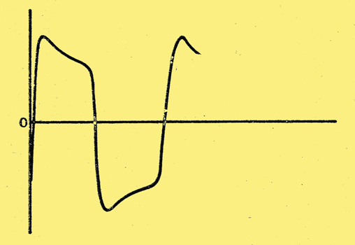
Fig. 4. - The voltage waveform of the output of a thyratron inverter.
Fig. 4 shows the output voltage waveform across a 400 Ω resistance load taken on a Cambridge Instrument electro-magnetic oscillograph. The peaks tend to flatten out as the load increases.
|