|
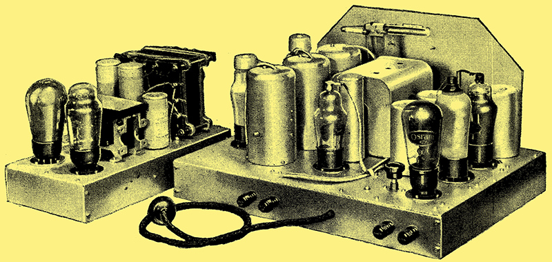
A highly sensitive quality receiver with variable selectivity and QAVC. The attainment of the highest standard of both selectivity and quality demands the possibility of varying the selectivity to suit receiving conditions. Recent articles in The Wireless World have dealt at length with the necessity for variable selectivity and it is included in this latest model of the Monodial. In addition, the features include an efficient AVC system together with an automatic muting circuit for inter-station noise-suppression, while an unusually high degree of pre-selection is used to avoid difficulty from heterodyne whistles.
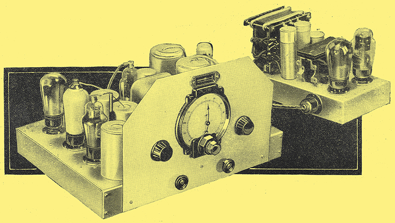
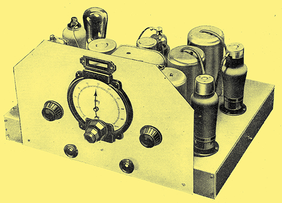
In this view of the receiver, the escutcheon for the neon tuning indicator can be seen immediately above the dial.
The characteristics of a receiver intended to give the best results under the widely varying conditions involved in any but local reception have been discussed in detail in recent issues of The Wireless World [★] See right menu for details, and it was shown that variable selectivity is essential to the attainment from every station of the highest standard of reproduction possible under the particular interference conditions existing at the moment of reception. Without variable selectivity, the quality is usually poorer than it need be or the interference is greater, for a fixed degree of selectivity can suit only particular conditions.
Variable selectivity is most readily obtained at an intermediate frequency which lies between the two wave-bands devoted to broadcasting, and such a frequency has the further advantage of reducing the amount of pre-selection necessary for the elimination of second-channel interference, even under poor receiving conditions. A signal-frequency HF stage is desirable in order to keep background hiss at a minimum, while an efficient frequency changer operating under optimum conditions is important.
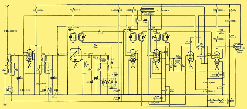
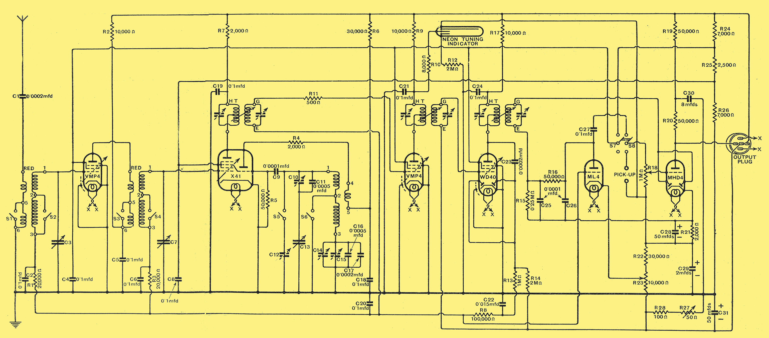
The complete circuit diagram of the receiver.
Valve line-up: VMP4, X41, WD40, ML4, MHD4, N41 and MU14.
The complete circuit diagram of the receiver unit is shown in Fig. 1, and. it will be seen to include a total of six valves of which one is employed for signal-frequency amplification and another for the frequency-changer. Two valves are used in the IF amplifier, the first providing amplification only and the second both amplification and automatic volume control. The fifth,valve is a combined detector and LF amplifier, while the sixth provides the muting action of QAVC.
The Signal-frequency Circuits
The HF valve is an HF pentode of high internal AC resistance and mutual conductance, and it is preceded by a single tuned circuit, the coil of which is tuned by one section C3 of the three-gang capacitor. The medium- and long-wave coils are connected in series in the usual manner, and on the medium Waveband the long-wave section is short-circuited by the switch S2. Separate windings are used for the aerial circuit, and here, again, the long-wave coil is short-circuited on the medium Waveband by the switch S1. A capacitor C1 of 0.0002 μF capacity is included in series with the aerial and serves to reduce the effective coupling to the correct degree for this receiver. The use of this capacitor also permits the circuit conditions to be readily changed by altering the value of C1 should the use of an unusual type of aerial render this desirable. The cathode of the HF valve is earthed, and the grid potential is derived from the AVC line through the 20,000 Ω resistance R1 the 0.1 μF capacitor C2 acting to complete the tuned circuit and to provide decoupling in conjunction with R1.
The coupling between the HF and frequency-changer valves is by means of an HF transformer having a secondary circuit identical with that preceding the HF valve, and tuned by the second section C7 of the gang capacitor. As in the case of the first valve, the grid potential of the frequency changer is derived from the AVC line, and the decoupling components C6 and R3 are given identical values in order to ensure accurate ganging. The primary of the transformer has fewer turns than the secondary, in order to keep the stage gain at a reasonably low figure and to restrict the stray capacity effective in the secondary circuit. Wave-changing is accomplished by the two switches S3 and S4, which short circuit the long wave sections of the primary and secondary respectively, while the anode of the valve is decoupled by the 10,000 Ω resistance R2 and the 0.1 μF capacitor C5.
For the frequency-changer the new triode-hexode valve is employed, and this is really two valves in a single envelope a hexode acting as a mixer and a triode functioning as an oscillator, the coupling being electronic. The oscillator circuit is entirely conventional, its apparent complexity being due merely to the ganging arrangements. It is of the grid leak type, the grid capacitor C9 having a capacity of 0.0001 μF and the leak R5 a value of 50,000 Ω. The coil is so designed that the reaction coil does not need switching, so that the anode circuit of the valve is quite straightforward, decoupling and the maintenance of the correct voltage being secured by means of R6 and C18. The 2,000 Ω resistance R4 is included in order to prevent large changes in the amplitude of oscillation with the tuning.
The details of the tuned circuit in the oscillator grid circuit will repay careful examination. This circuit must at all times be tuned to a frequency 465 kHz higher than the two signal frequency circuits, and the various capacitors shown on the diagram are necessary to achieve this. Wave changing is accomplished by S5 and S6, which are actually incorporated in a single switch. When S6 is closed S5 is open, and vice versa, and S6 closes at the same time as S1, S2, S3, and S4. This is for the medium waveband, and it will be seen that the medium wave coil between terminals 1 and 2 of the coil assembly is then connected directly to the earth line. This coil has an inductance of 71.5 μH. as compared with 163.5 μH. for the signal-frequency coils, and it is tuned by the third section C13 of the gang capacitor - a section which has connected in series with it the padding capacitors C10 and C11. Of these C10 is an adjustable trimmer with a maximum capacity of some 240 pF, while C11 is a fixed capacitor of 500 pF. By the use of the two capacitors in this way the range of capacity is limited, and while it is possible to adjust it to exactly the required value, it is impossible for the circuit to be very widely out of adjustment. If a single trimmer of high capacity were employed, this would not be the case, and the initial adjustments would become more difficult. The parallel trimmer for this waveband is not shown on the circuit diagram, since it is a part of the gang capacitor and appears across C13 just as the other trimmers appear across C3 and C7.
On the long waveband S6 is open and S5 closed; the oscillator inductance is then 196.5 μH as compared with 2,190 μH for the pre-selector. No provision for ganging on this waveband is considered necessary in the signal-frequency circuits, in accordance with the usual practice, but both the series and the parallel capacities must be changed in the oscillator circuit. The parallel capacity must be increased by some 157 pF and the trimmer C12 of 240 pF maximum capacity is accordingly switched in circuit. The padding capacity required is less than on the medium waveband, so that it is possible to insert the long-wave capacitor in series with it and thus save switching. The combination of capacitors C14, C15, C16 and C17 is employed. Of these, the two first are trimmers, but only one is used as such, the other being screwed up and used as a fixed capacitor. In addition to these, a capacity of 0.0007 μF is needed, and as this is not a standard value two capacitors in parallel are used, C16 of 0.0005 μF and C17 of 0.0002 μF.

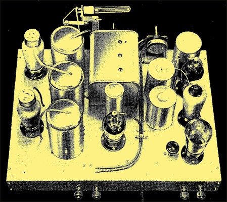
In this view of the receiver the muting valve and its control can be seen in the right-hand corner, and the initial sensitivity control projecting through the side of the chassis.
The IF Amplifier
Coupling between the oscillator and mixer is obtained in the valve, and the intermediate frequency appears in the hexode anode circuit, in which is connected the primary of the first IF transformer, decoupling being obtained by means of the 2,000 Ω resistance R7 and the 0.1 μF capacitor C19. The secondary of the transformer feeds the first IF valve through a 500 Ω resistance R11, which serves to prevent parasitic, oscillation; the lower end of the tuned circuit is returned to the AVC line, decoupling being provided by the 100,000 Ω resistance R8 and the 0.1 μF capacitor C20. Another transformer of identical characteristic couples the two IF valves, of which the first is an HF pentode and the second the combination of an HF pentode and a duo-diode. This second staged is not controlled for AVC purposes, so that the low potential side of the transformer secondary in its grid circuit is returned to negative HT; as the cathode is taken to the earth line which is about 3 Volts positive with respect to this point, a fixed negative grid bias, of some 3 Volts is obtained.
The two diodes in this valve are strapped together and used to provide the AVC voltage. They are fed from the anode circuit through the 0.0002 μF capacitor C23 and their load resistance R14 of 2 M Ω is taken to negative HT. A filter stage comprising the 1 M Ω resistance R13 and the 0.015 μF capacitor C22 is connected as closely to this valve as possible in order to prevent feedback effects occurring along the AVC line. It will be seen that in the absence of a signal the first four valves all have the same initial bias, and that this voltage is applied also as delay to the AVC diodes. When a signal is tuned in these conditions remain unaltered until the output of the second IF valve exceeds about 3 Volts peak. Rectification then occurs in the diode circuit and a potential appears across R14 in such a direction as to make the diode anodes negative with respect to negative HT. The grids of the first three valves are connected to the diode anodes through the decoupling system, so that they acquire the same potential. As the output of the second IF valve increases, therefore, the potential across R14 increases, and also the negative bias on the controlled valves with the result that their amplification decreases. If only weak signals were involved the second IF stage could be controlled in addition to the others, but this is not permissible with a strong signal for severe overloading would be likely to occur.
The next valve in the chain is a duo-diode-triode which functions not only as the detector but also as an LF amplifier. The coupling between the IF valve and detector is by means of an IF transformer, which, like the other two, has variable coupling between its coils. The three transformers are mechanically linked together and the coupling can consequently be altered by a single panel control for variable selectivity. The two diodes of the duo-diode-triode are strapped together and act as the detector. The load resistance R15 of 0.25 M Ω is returned directly to the cathode and the by-pass capacitor C25 is given the usual value of 0.0001 μF In place of the HF choke normally employed in the filter circuit a resistance R16 of 50,000 Ω is used in conjunction with the 0.0001 μF capacitor C26. The resistance provides adequate filtering and is less expensive than a choke.
The LF potentials which appear across R15 as a result of detection are communicated to the grid of the triode section of the valve through the 0.1 μF capacitor C27 and the volume control R18. This volume control is given ba value of 1 MΩ, for in order to avoid detector distortion on deep modulation it is necessary for it to have at least 2.5 times the value of the detector load resistance. The control functions both on radio and on gramophone, the change-over being effected by S8, while S7 removes the screen voltage from certain valves to prevent interference from radio signals when operating on gramophone.
The Muting Circuit
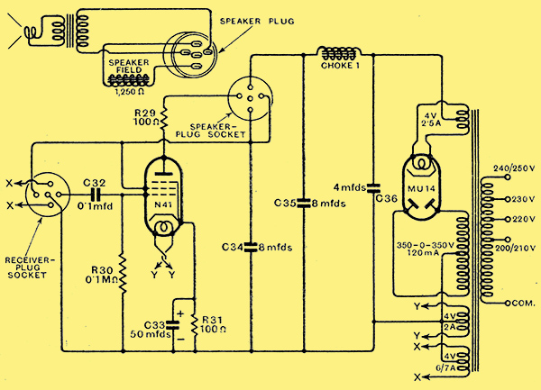
Fig. 2. - The power unit is of conventional design employing a high-efficiency pentode output valve.
Grid bias for the LF valve is obtained from the voltage drop across the 2,000 Ω resistance R21 in its cathode circuit; this resistance is shunted by a 50 μF electrolytic capacitor C28 in order to avoid feed-back effects. In the anode circuit a 50,000 Ω coupling resistance is used, and the grid of the pentode output valve (Fig. 2) is connected to the anode of the LF valve through the 0.1 μF coupling capacitor C32. Decoupling of the valve is provided by the 50,000 Ω resistance R19 and the 8 μF capacitor C30. The output stage is entirely conventional, using one of the high-efficiency pentodes giving an output of some 3.5 Watts for a very modest signal input. The mains equipment also follows the usual practice, an indirectly heated rectifier valve being used with a 4 μF reservoir capacitor C36. Initial smoothing is provided by Ch1 and C35, and final smoothing by the loud speaker field winding and C34. The loud-speaker field must have a resistance of 1,250 Ω.
The rectifier valve is an MU14 in spite of being fed only with 350 Volts from the mains transformer. This valve has been selected because it has a lower resistance than one of 350 Volts rating only, and it can consequently provide a somewhat larger rectified output while still employing a transformer of standard rating.
So far no mention has been made of the triode valve which is associated with the detector. This gives the muting action of QAVC and silences the set when it is not tuned to a station. The cathode of the detector is returned to negative HT through resistances totalling some 42,000 Ω so that its potential is about 45 Volts positive. The anode of the muting valve is taken to the detector cathode through R15 and R16, totalling 300,000 Ω, and its cathode is taken to the slider of R23. Its grid is joined to the AVC line.
Now, in the absence of a signal the grid potential of this triode is the voltage existing between the slider of R23 and negative HT, and its anode is taken through its load resistance to the detector cathode, which is positive with respect to the triode cathode. The muting control R23 is adjusted to give potentials such that the triode passes anode current. This current passes through R15 and R16, and the triode anode is consequently negative with respect to the detector cathode, and as the diode anodes are joined to the triode anode through R16, they are negative with respect to their own cathode. The detector has thus a negative bias and is inoperative.
When a signal of sufficient intensity is tuned in the triode grid receives additional negative bias from the AVC system, and this reduces the triode anode current to zero, and so removes the negative bias from the detector and permits it to function normally. The precise signal strength at which the system operates is adjustable by R23, and a wide range: of control is obtained. At one end of the travel of the slider no muting at all occurs; while at the other only a powerful local station will release the detector. The normal condition, of course, is such that with the set tuned to no signal background noise is just eliminated.
In common with all QAVC systems there is a certain range of signal strengths over which severe distortion occurs, corresponding to the signals for which the muting valve only partially releases the detector bias. This range of signals is small, and with the normal adjustment corresponds to very weak stations indeed; stations, in fact, whose level is so near that of the prevailing background noise that their programmes would, in any case, hardly prove of entertainment value.
The tuning indicator is of the neon type. As can be seen from the circuit diagram, one electrode is returned to the earth line through a 2 MΩ resistance R12, and another is taken to the detector cathode to secure the requisite positive potential. The control electrode is joined to the first IF valve anode circuit, the change of voltage across R9 with changing AVC voltage causing an alteration in the glow from the tube.
High Tension Supply

A view of the power unit which contains not only the mains equipment but also the output stage.
The voltages for operating the valves are secured in the simplest manner from a voltage divider across the HT line of some 250 Volts. This comprises the resistances R24, R25, R26, R27 and R28, and supplies of 100 Volts for the screens of the HF and IF valves are available as well as 70 Volts for the frequency-changer screen, and 3 Volts for grid bias. This latter potential has been made adjustable by means of a pre-set type of variable resistance R27 in order that compensation may readily be obtained for the effects of the inevitable variations in valves and components. Were a fixed resistance to be used, abnormally low amplification might be found in some sets, and instability in others, and the inclusion of this resistance renders it possible to adjust the amplification to the same degree in all receivers.
Turning now to the power unit, a pentode output valve is used and resistance-coupled to the preceding stage, the grid capacitor C32 being given a capacity of 0.1 μF and the grid leak R30 a value of 0.1 Ω. Grid bias is derived from the voltage drop across the 100 Ω resistance R31 in the cathode circuit which is shunted by a 50 μF electrolytic capacitor C33. A 100 Ω anti-parasitic resistance is included in the anode circuit.
Construction
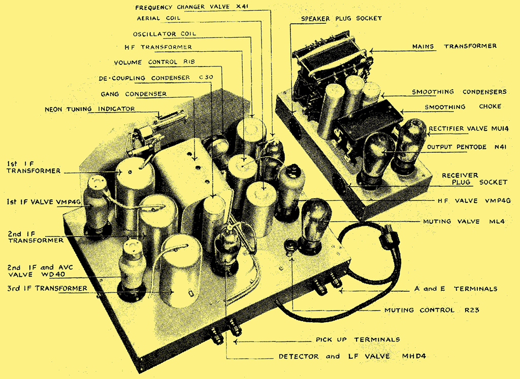
The panel controls are clearly shown in this photograph, while the IF amplifier is visible on the right.
The components are assembled on two aluminium chassis, one for the receiver proper and the other for the output stage and mains equipment. No difficulty will be found in the mechanical construction, and with one or two minor exceptions the order in which the components are mounted is unimportant. The gang-capacitor, however, should be left to the last. When fitting the switches, fix each to the chassis by its nuts and bolts, but leave these quite loose; then insert the control rod, and only tighten the fixing nuts when this rod is in place. If this procedure is not adopted it will probably prove impossible to insert the rod. Before tightening the set screws on each switch, make sure that they all lie to the same side of the centre line. The control knob for the switches has a standard ¼ in. bush, but as the shaft is of smaller diameter a liner is employed, and when inserting it into the knob it is important to see that the slit side of the liner is away from the grub screw, otherwise it will not grip the shaft.
When the components have been mounted, solder five long wires to the tags on the under side of the gang capacitor, three for the fixed plates and two for the frame. Pass these wires through the holes provided in the chassis and secure the capacitor.
The wiring should now be commenced, and will be found straightforward and devoid of pitfalls if the details given in the drawings and photographs are carefully followed. It is, however, of greater importance than is often realised to follow the design in the matter of the physical positions of the wires. The general run of the wiring is usually at least as important as the layout of components, for in these days of screened components changes in their positions usually affect the performance only by the changes in the wiring which necessarily follow.
The Wiring
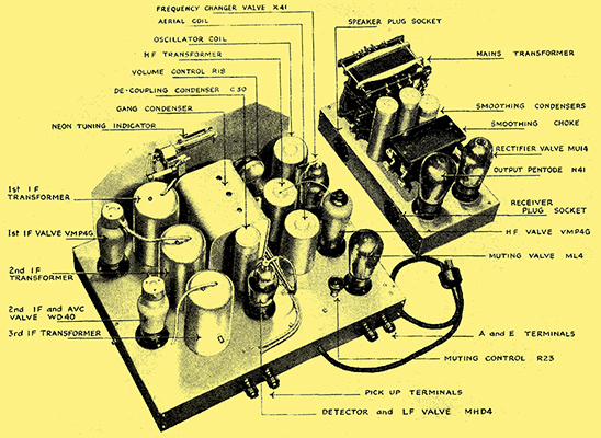
In this view of the apparatus the chief components can readily be seen. The three IF transformers are mounted in a row and the selectivity can be varied by means of a shaft passing through them.
Considerable effort has been expended upon obtaining an arrangement of the wiring which would meet the electrical requirements fully and yet be mechanically rigid and simple enough to depict clearly in a drawing. Although changes in certain leads will have no effect whatever upon the performance, alterations in others may easily cause instability or some other defect; consequently, a change in the wiring can be considered no more legitimate than a modification in the positions of the components. It is in order that the wiring of the original receiver may be closely followed that the practical wiring diagram is included in this article, and it is recommended that full use be made of it. Were the positions of the leads unimportant, there would be no reason for publishing such a diagram; the wiring could be perfectly well carried out from the circuit diagram alone, if it were important only that the correct points be joined together.
No. 16 gauge wire is used for the heater connections, and it is advised that these leads be first placed in position, since the wire is very stiff. It should, of course, be straightened by stretching it slightly. It is used also for a few other leads Where special rigidity is advisable. The rest of the wiring is carried out with No. 18 or No. 20 wire, according to preference. No. 18 is preferable in many cases on account of its greater stiffness, but nothing larger than No. 20 should be used in the case of the screened leads.
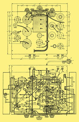
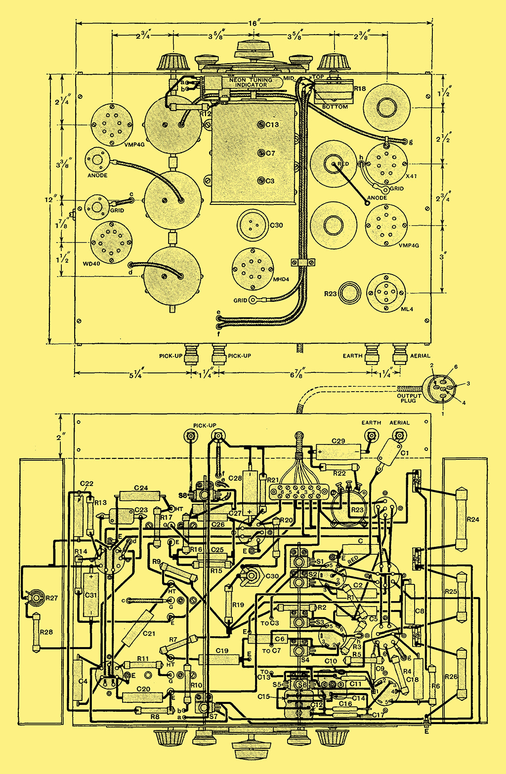
Full details of the wiring and layout of components are shown in these drawings. It is important that the layout of the wiring should be followed closely if unwanted couplings are not to be introduced.
It may be remarked that the screened leads are earthed by clamping them to the chassis by metal straps. Soldered connections to the metal braiding should not be made, for it has proved almost impossible to solder the braiding without charring the insulation, and a breakdown sooner or later is then almost a certainty. Such breakdowns are often intermittent and quite difficult to trace, so that it is as well to remove 90% of their possibility by refraining from soldering in such cases. Flex leads are fitted to the IF transformers. These should be cut to the correct length and pieces of screened sleeving pushed over them, the metal braiding just being allowed to pass inside the screening cans.
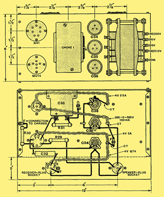
The details of the power unit are shown in these drawings. Few under base componentsare fitted and the wiring is straightforward.
The resistances and many of the capacitors employed are fitted with wire ends of lengths varying from 1½ in. to 3 in. In many cases they are longer than necessary, and where this is so they should be cut short. Remember that the leads to a bypass capacitors are carrying HF or IF currents, and the longer the leads the greater the chance of unwanted coupling between different circuits. The case is similar with resistances, particularly those joined in the anode or grid circuit of valve.
The Initial Adjustments
.
If these points be borne in mind, and the wiring plan carefully followed, there is no reason to anticipate difficulty in getting the receiver to function, and the set should operate perfectly as soon as the necessary initial adjustments have been made. When setting up the set, insert all valves except the muting valve and switch on. After allowing a short time for the valves to warm up, check over the voltages and currents and make sure that they are reasonably in accordance with the figures in the accompanying table.
They are unlikely to agree exactly, for they will be affected not only by the permissible variations in resistances, valves, transformers, and mains, but by the accuracy of the meter used and the value of its internal resistance. Variations of about plus or minus 10%, therefore, are usually negligible, and 15% is not serious, particularly if they are consistent. If one circuit shows a high voltage accompanied by a low current, however, then it must be taken as an indication of a probable fault in that circuit a valve, resistance, or capacitor being the probable cause, or else a mistake in the wiring. It may be remarked that the resistances R24, R25, and R26 in the voltage divider dissipate a fair amount of heat, and the fact that they are hot to the touch is no indication of anything amiss.
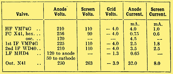
The trimmers on the gang capacitor are here lettered D, E, and F, referring to the trimmers on the capacitor sections C13, C7, and C3. The trimmers A, B, and C on the IF transformers are in every case primary trimmers on the 1st, 2nd, and 3rd transformers respectively.
The initial adjustments are chiefly to the ganging, and although this may quite well be carried out without additional equipment, it is more easily done if a calibrated oscillator, which need not be modulated, be available. Assuming that such an oscillator can be used, set it at 465 kHz, insert a capacitor in series with its high potential output, lead, and connect it between the grid (top cap WD40) of the second IF valve and the chassis. Loosen the IF transformer coupling nearly to minimum by turning the control knob in an anti-clockwise direction almost as far as it will go. Then trim the third IF transformer primary circuit (top trimmer, rear can) for maximum response as indicated by maximum deflection on the neon tuning indicator. Then trim the secondary (bottom trimmer, rear can) for maximum volume from the loud speaker it the oscillator be modulated. If it is not modulated the setting can usually be determined by the appearance of a slight hiss at resonance, while the tuning indicator will drop back very slightly.
Having adjusted these two circuits, transfer the oscillator high potential lead to the first IF valve grid and adjust first the secondary (bottom trimmer) and then the primary (top trimmer) of the second transformer (middle can) for maximum deflection of the indicator. A smaller output from the oscillator is advisable on account of the greater amplification now in use. Next clip the oscillator lead to the frequency-changer grid (top cap), and similarly adjust the two trimmers on the first transformer (front can). The IF circuits are now all tuned to 465 KHz, and should require no further attention. It is worth taking some pains to secure precision of setting of the trimmers, for the adjacent channel selectivity depends entirely upon the accuracy of adjustment. As a safeguard, therefore, it is advisable to check the adjustment of each trimmer before proceeding farther, but this time the oscillator can be left connected to the frequency-changer.
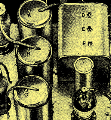
The trimming capacitors are readily adjusted by means of an insulated screwdriver. C10 is the medium wave and C14 the long wave padding capacitor, while C12 is the long wave parallel trimming capacitor.
The next step is to adjust the ganging. Connect the oscillator to the aerial and earth terminals, preferably through an artificial aerial, but, if not, through a 0.0002 μF capacitor , and set it at 1,500 kHz (200 metres). Set the tuning dial at zero, and the wave-range switch for the medium waveband. Short-circuit the oscillator coil by a short lead terminating in spring clips by connecting the junction of C9 and C10 to the chassis. This will prevent the oscillator from functioning. Set the external oscillator to give a large output (0.1 - 1.0 Volt), and adjust the trimmers on C3 and C7 for maximum deflection on the indicator; the trimmer on C3 will be nearly fully unscrewed. A large input to the set is necessary for adjusting in this manner, for the procedure depends upon grid current flowing in the HF or FC valves; the grid current causes a potential to appear on the AVC line and changes the current through the first IF valve, so operating the tuning indicator.
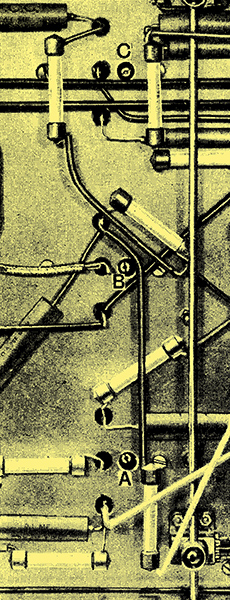
In this view of the receiver the secondary IF transformer trimmers can be seen and are again lettered A, B, and C for the 1st, 2nd, and 3rd transformers.
Having adjusted the two trimmers, set the oscillator to 1,400 kHz and tune the set to this frequency by the tuning dial, again using the neon tube as an indicator of the precise setting. Now reduce the output of the oscillator well below the point at which the tube ceases to give an indication. Remove the short-circuit from the set oscillator, and adjust the trimmer on C13 for maximum response. The setting of this trimmer is quite critical. If more than one point of response be found, select the strongest, and this is most easily done by reducing the input until only one can be found. The next step is to replace the short-circuit on the set oscillator, set the ganging oscillator to 600 kHz (500 metres), and with a large output tune the set to it. Then reduce the oscillator output, remove the short-circuit from the set oscillator, and adjust C10 for maximum response. This setting is critical, and the output from the oscillator should be no more than is necessary to obtain an adequate deflection.
A return to 1,400 kHz should now be made, and the trimmer on C13 adjusted exactly as described before. The setting found for it this time will probably be only very slightly different from the one found at first. This completes the medium-wave ganging, and it is now the turn of the long waveband. This is done in a similar manner to the medium, but there are fewer adjustments.
Set the oscillator to 300 kHz (1,000 metres), and, of course, the wave-range switch to the long waveband, and stop the set oscillator from functioning. Tune the set to 300 kHz by the main tuning control, using, of course, a large output from the oscillator. Reduce the input to the set, remove the short-circuit from the set oscillator, and adjust C12, being careful to keep the input to the set small enough for only the strongest response to be obtained. Replace the short-circuit on the set oscillator, adjust the external oscillator to give a large output at 160 kHz (1,875 metres), and tune the set to it. Remove the short-circuit, reduce the input, and adjust C14. It may be found that varying this capacitor has little effect. This is because the possible variation represents only a small proportion of the total capacity. In many cases it is hardly necessary to adjust this trimmer, and it is really included only to permit of compensation for variations in the capacities of the fixed portion of the padding.
The Muting Circuit
Top view of chassis.
The ganging is now completed, and it only remains to adjust C3 to suit the actual aerial which is to be used. To do this, tune in a medium-wave station on as low a wavelength as possible, and adjust C3 for maximum response. The muting valve may now be inserted and its control R23 suitably adjusted to suit individual requirements. Experience has shown the ML4 valve to give the best control, but almost any triode will function quite well, and such a different type as the MH4 is very nearly as good. When R23 is fully rotated in a clockwise direction, no muting will be obtained, and when it is fully turned the opposite way, only strong signals will be audible. To adjust R23, tune the set to a point where the background is greatest, the set being tuned to no signal, and slowly turn R23 until silence is just, and only just, secured. It should then be found possible to tune from one end of the scale to the other with the stations suddenly appearing out of a dead silent background. With the set adjusted for maximum selectivity, muting will be obtained between channels in many cases, but not usually when this control is in the high-fidelity position. This is not important, for the same action which prevents muting prevents the sensitivity rising sufficiently for background noises to become obtrusive.
Now, although an oscillator is a very desirable aid to the correct adjustment of the receiver, it is by no means impossible. correctly to gang the set without one, and as the procedure is necessarily somewhat different, this will now be dealt with. Remove the muting valve, and screw each IF trimmer fully home, and then unscrew each trimmer one half-turn. The circuits are then very roughly adjusted to 465 kHz, and the next step is to adjust them accurately. To do this, set the selectivity control at minimum selectivity that is, fully rotated in a clockwise direction, and tune in a signal. If this be strong, turn the control the other way until it can only just be heard, and adjust each IF trimmer roughly for maximum signals. This will greatly increase the sensitivity, and it should not be difficult to find a station of such strength that a good deflection is obtained on the tuning indicator with the selectivity control nearly fully rotated in an anti-clockwise direction. Each IF trimmer in turn must now be adjusted for maximum response. Start with the secondary of the third transformer and use the ear as an indicator of volume, then proceed to the primary, and thence to the secondary of the second transformer, and so on, for these five using the tuning indicator. This completes the IF adjustment, and it is the turn of the ganging, which must first be carried out on the medium waveband.
Ganging on a Signal
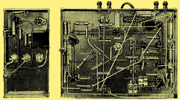
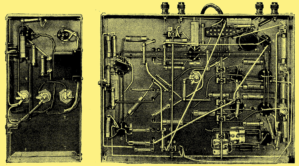
The wiring is clearly shown in these views of the receiver and power chassis. Note the initial sensitivity control R27, which projects through the side of the receiver chassis on the left in the illustration.
Unscrew C3 nearly fully, and C7 not quite as much. Adjust C13 to have roughly the same capacity as C7, or a little more. Tune in a medium-wave station on as low a wavelength as possible, and adjust C3 and C7 for maximum response. If this leads to C3 being screwed up considerably, reduce C13 slightly and retune; on the other hand, if no optimum setting for C3 can be found, increase C13 and retune. It should be noted that the trimming on C3 is very flat, and care must be taken in determining the indications. If the set is being used near a local station of low wavelength, such as the London National, a somewhat simpler method is possible. The trimmers should be set as before, and the oscillator stopped by short-circuiting its grid coil as described under ganging with a test oscillator. Tune the set to the station by noting the resonance condition on the tuning indicator, and adjust C3 and C7. Then remove the short-circuit from the oscillator and adjust C15 for maximum response, being careful to choose the strongest if more than one point can be found.
When satisfied with the adjustment, tune in a station at the upper end of the waveband Brussels on 620 kHz if possible-and adjust C10 while rocking the tuning dial backwards and forwards until the optimum combination of settings be found. Then return to a weak low-wave-length station and readjust C3 and C7. On the long waveband, set the tuning dial to receive Droitwich and adjust C12 for maximum volume from this station. Then if possible find a lower wavelength station, such as Oslo, and adjust C12 while rocking the tuning dial for the best combination of settings. C14 is then adjusted in the same way, but on Huizen; as already explained, however, this last adjustment is usually unnecessary.
Before concluding the discussion on the adjustment, a few remarks about the tuning indicator may be advisable. The values assigned to the different components have been chosen to give good indication, and no change should be needed with normal tubes. When the set is tuned to no signal the glow should extend about one-half inch up the tube, and it should fill the tube when the set is tuned to the local station. If the glow be too great the voltage drop across R22 is not enough, and the value of this resistance should be increased. On the other hand, a reduction of this resistance is called for if the glow is not great enough.
Turning now to the question of the performance, this should be of the same order as that obtained from the original receiver, and an indication of the performance to be expected, therefore, is best given by describing the results obtained from a test on the original set. The quality of reproduction reached a very high standard with the selectivity control set for low selectivity. The measured frequency response of the receiver showed a falling characteristic at the highest audible frequencies, but this is automatically corrected by the rising response obtained by the combination of the loud speaker and the pentode output valve. The result is that frequencies as high as 8,000 Hz are adequately reproduced, With this degree of selectivity, many of the stronger Continental stations can be received well in daylight, but at night a higher degree of selectivity becomes necessary for the reception of those stations which have neighbours of equal or greater strength.
As the selectivity is increased the sensitivity rises slightly and then starts to decrease, and the highest selectivity is accompanied by a considerable drop in sensitivity. The initial sensitivity, however, is so high that this is unimportant, and the effect is barely noticeable, for AVC takes up the variations in volume which it would otherwise cause. With the selectivity nearly at its maximum it has proved easily possible to receive the Deutschland-sender in daylight when both Droitwich and Radio-Paris are working. No intelligible modulation interference was found in the tests, but sideband splash prevented the enjoyment of music, although speech could be followed with ease. On reducing the selectivity the programme was completely swamped by Droitwich. At all points in the range the selectivity proved adequate for distant reception and could be reduced when interference permitted to allow of a very high standard of quality being obtained. The sensitivity proved higher than is necessary for most purposes when a good aerial is used, but the reserve of power which it gave proved its worth in enabling the AVC system to function as a true anti-fading device.
On every station giving an adequate signal to external noise ratio for enjoyable reception, internally generated noise proved negligible; valve hiss and mains hum were inaudible. During the tests local interference was exceptionally severe, being perhaps a hundred times as great as in the average house, and amply demonstrated the value of QAVC. Without this fitting the noise while tuning was intolerable unless the manual volume control was kept at a very low level. With the muting valve in circuit, however, complete silence was secured between stations, save for occasional clicks when an extra strong pulse of interference momentarily released the detector. No aurally detectable difference in the quality could be found on any worth-while station, whether the muting were operative or not, and in normal operation the risk of distortion on weak signals is less, for muting can safely be adjusted to function on weaker signals. In order to avoid misconception it may be as well to point out clearly that the muting circuit only eliminates noise while tuning, in fact, when the set is not tuned to a signal. When the set is tuned to a station the muting circuit does nothing to reduce noise of any kind.
The manual volume control functioned smoothly and gave an entirely adequate range of control. It functions on radio and gramophone, but owing to its high resistance and the fact that a pentode output valve is used it may prove necessary to shunt the pick-up terminals with a resistance in order to prevent excessively high-pitched reproduction. The value should be found by trial and will depend upon the pick-up employed; it will usually lie between 50,000 Ω and 0.25 MΩ, however. It should be remembered that the pick-up terminals are about 50 Volts above earth potential, so that care should be taken to avoid a short-circuit to earth.
It is regretted that an error occurred in both the circuit diagram and list of parts. The TCC Type 250 0.1 μF tubular capacitor C was omitted. This capacitor is joined between the heater of the HF valve and the chassis.
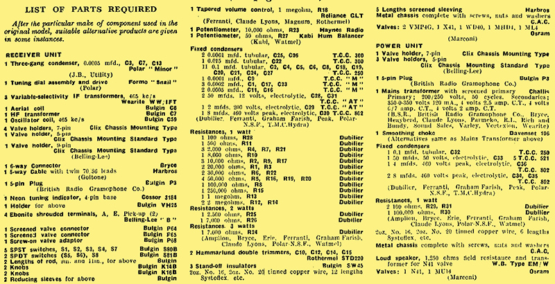
The WBType EM/W loud speaker specified
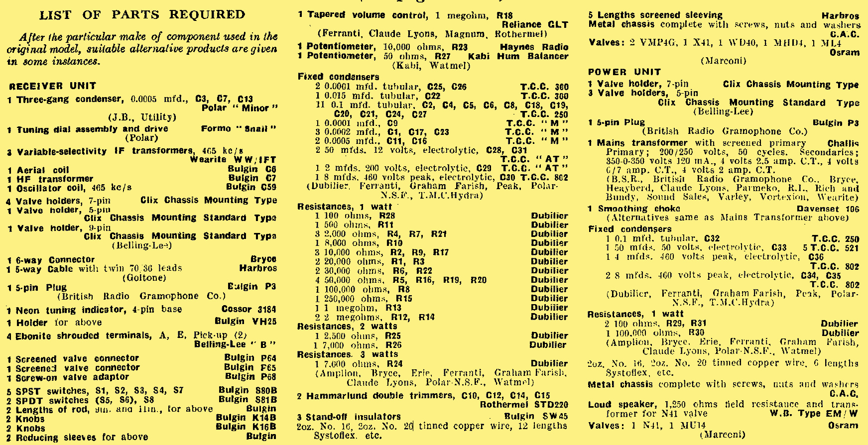
Complete list of parts.
New Rola Loud Speaker
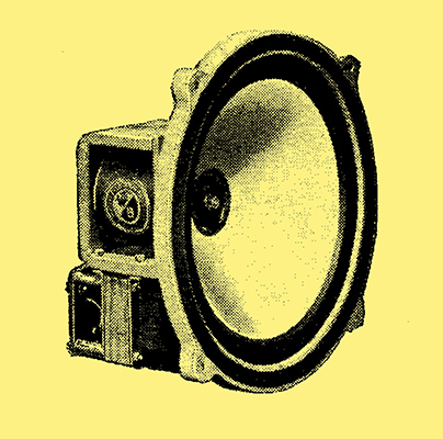
The Rola G12 loud speaker.
A loudspeaker has been submitted for test by the British Rola Co., Ltd., of Minerva Road, Park Royal, London, NW10, as being specially suitable for The Wireless World 1936 Monodial AC Super. It is of massive construction and provided with a field winding having a resistance of 1,250 Ω, and so suitable for energising from the mains equipment. The transformer included is of suitable ratio for matching the N41 valve.
The cone is of the corrugated type with a free suspension, while the centring device gives a minimum of constraint to its movement. On test, the speaker functioned well, the sensitivity being high and the reproduction free from noticeable resonances, while both bass and treble were well maintained.
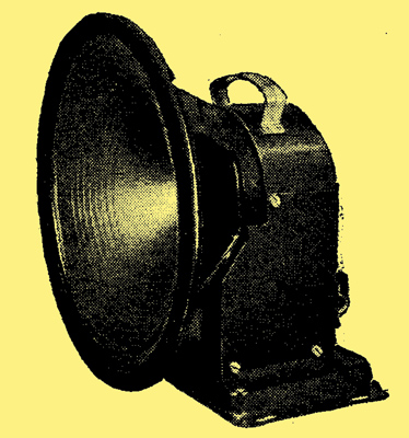
Wound Components
The Bryce smoothing choke for The Wireless World 1936 Monodial AC Super is shown on the left and the mains transformer in the centre. The components are well built and the transformer is fitted with leading out wires. The Sound Sales choke for this set is shown on the right. It is ruggedly constructed and has an inductance of 10 H. with a resistance of 120 Ω, and will carry 120 mA.
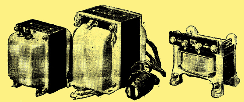
Cover advert for the three gang variable capacitor.
|