|
Since the requirements of selectivity and quality are conflicting, it is clear that the ideal receiver would be fitted with variable selectivity in order that the optimum; conditions for any and every station may be realised. The attainment of variable selectivity has hitherto proved difficult, but it is shown in this article that it is by no means hard to obtain a wide range of control if the design be carried out correctly.
At a time when the attainment of the highest standard of quality demands the retention of modulation frequencies up to 10,000 Hz and the requirements of selectivity necessitate the sacrifice of frequencies higher than 4,000 Hz, it is clear that some compromise between selectivity and quality is essential. The most pleasing result to the ear is not secured by perfection of reproduction if this entails a large degree of interference, nor is it given by complete absence of all interference if this leads to the absence of the entire upper register from the reproduction. Most listeners prefer a compromise between the two extremes, for few will dispute that a pleasanter effect is obtained when the quality is sacrificed only as far as is necessary to reduce interference to the point at which it is not intrusive although it may not be completely inaudible.
It will be clear, therefore, that since the interference conditions are different for every station, and even vary frequently for each station, the optimum degree of selectivity must also vary for every station, and will be different for the reception of the same station in different localities. The ideal receiver would consequently be fitted with continuously variable selectivity so that its characteristics could be altered at will to suit the particular receiving conditions existing at any moment and in any district. This has long been recognised, but it is surprisingly difficult to devise a means of varying the selectivity of at receiver which is satisfactory from all points of view, and it is only recently that any considerable degree of success has attended the efforts of designers.
There are two distinct methods of obtaining variable selectivity. With the first, the inherent selectivity is of such an order that no serious degree of sideband cutting occurs, and it is increased when necessary by the application of reaction. This method has been adopted in the Single-Span receivers so far described in The Wireless World, and it has the great merit of simplicity. It is, however, open to the objection that the degree of selectivity obtainable is limited by the appearance of self-oscillation. With the second method, the inherent selectivity is made as high as the designer judges necessary for the avoidance of interference, and it is reducible by some means for reception under conditions of moderate or little interference. A much wider range of control is possible in this way, and it is the means to be adopted which we have now to consider.
Methods of Varying Selectivity

Fig. 1. - The selectivity of a single circuit can be varied by means of a series variable resistance, (a) of low value or a shunt resistance, (b) of high value.
Since the selectivity of a tuned circuit depends upon the Q( ωL/R R = reactance / resistance) of the circuit, and the inductance must normally be fixed, an obvious method of varying the selectivity is to vary the resistance. This may be done in two ways: a variable resistance of low value can be connected in series with the circuit as shown in Fig. 1 (a), or one of high value in parallel as in Fig. 1 (b). Where only a single circuit need be controlled, either of these methods is satisfactory, although open to the objection that the sensitivity must vary also. When we remember, however, that the IF amplifier of a modern superheterodyne may contain as many as six tuned circuits, we can see that the control of one circuit alone is likely to have little effect. Even if its selectivity were completely destroyed, the remaining circuits would normally cause excessive sideband cutting. Each circuit must be controlled if satisfactory results are to be secured, and the difficulties of controlling six circuits by this means are obvious, for six variable resistances, each independently screened, and ganged for operation by a common spindle, would be needed!

Fig. 2. - The resonance curve given by a pair of coupled tuned circuits varies with the degree of coupling. With loose coupling, it is sharp (A) but with optimum coupling (B) it is still single-peaked, while with tighter coupling (C) two peaks appear.
Now, in IF amplifiers the tuned circuits are usually arranged in coupled pairs, and it is well known that the degree of selectivity obtained depends very greatly upon the coupling. If a pair of tuned circuits be coupled loosely together, the resonance curve takes the form shown by curve A of Fig. 2, while if 'optimum' coupling be used, the curve is broadened to the shape shown by B. If the coupling be still further increased, two humps appear (curve C) and the system becomes of the bandpass type, Unless the coils are of low Q it is inadvisable to couple them very tightly, otherwise the trough between the peaks becomes very pronounced. On the other hand, unless the circuits have a large value of Q the selectivity with loose coupling will be low.
Ideally, therefore, the resistance of the circuits should be increased with the coupling so that the double-hump appears only as a minor irregularity in an otherwise flat-topped response curve. So much depends on the band-width required, or, rather, the ratio of the resonance frequency to the band-width, that it is impossible to lay down any hard and fast rule, and experience shows that with a fairly high resonance frequency a variation of resistance is unnecessary for high quality sound reproduction.
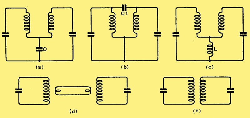
Fig. 3. - The chief methods of coupling circuits are shown here. At (a) the coupling is by common capacity and at (c) by common inductance, whereas with (b) a top-end capacity coupling is used. The link-filter is shown at (d) and mutual inductance coupling at (e).
Before going more deeply into this question it is as well to consider methods by which the coupling can be varied. The chief systems of coupling are shown in Fig. 3. With common capacity coupling (a) the bandwidth is controlled by the capacity of the capacity C. and it would appear that this would otter a simple means of obtaining continuously variable coupling by the use of a variable capacitor for C. There are two objections to this, however, and the first and less serious is the difficulty of obtaining a capacitor of large enough capacity, since a variation of some 0.005 μF would be needed. The second objection is that the response is not broadened by an increase in coupling an equal amount on either side of resonance.
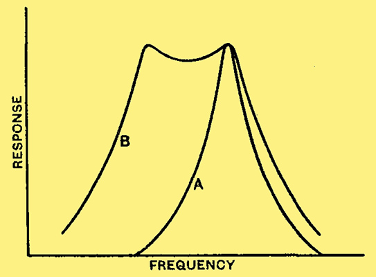
Fig. 4. - Certain methods of coupling give an unsymmetrical opening of the peaks. Curve (A) shows the results with loose coupling, and (B) when it is tight enough for the two peaks to appear.
Referring to Fig. 4, if A be the response curve with loose coupling, that with tight coupling takes the form of curve B. It can be seen that if a change be made in the coupling, the receiver must be retuned so that the carrier frequency lies in the centre of the resonance curve.
Filter Couplings
When top end coupling is used (b) the capacity of the coupling capacitor C1 is of more manageable proportions, being of the order of 1 pF. This circuit still suffers from the objection that the peaks do not open out symmetrically about the resonance frequency, but to one side, as in Fig, 4. The second peak occurs on the other side of resonance, however, and this applies also to inductive coupling (c). which has also the objection that a small variometer L would be needed to alter the coupling. Another and at first sight attractive circuit is link coupling (d), but this again suffers from the same disadvantage in the manner in which the peaks open out.
When we turn to the fifth circuit (e) in which the coupling is provided by the mutual inductance between the two coils, we find that, as long as the coupling is due to this alone, the peaks open out symmetrically, and we obtain the type of curve exhibited by Fig. 2. This system of coupling is thus the only one which theoretically can give the desired results, and, as practice amply supports theory, it is accordingly the only method which need be considered.
Before we can consider the precise arrangement which we can adopt, it is necessary to decide on the coils which are to be used, for the degree of coupling necessary will depend on their efficiency. We shall, moreover, confine the discussion to intermediate frequencies of the order of 465 kHz, for it is not difficult to demonstrate that with a lower frequency of some 110 kHz it is desirable to increase the circuit resistance with the coupling in order to prevent the appearance of excessively prominent humps in the response curve. Moreover, the use of low intermediate frequencies is less prevalent than formerly on account of the greater ease of elimination of second-channel interference with a moderately high frequency.
In designing a coil we have not only to consider the efficiency of the coil alone but its efficiency when connected in circuit and used with its tuning capacitor. At the frequencies under consideration, dielectric losses in the capacitor, valve-holder and valve base are by no means negligible, and profoundly influence the choice of a coil. Compactness is also a point of importance, and it is hardly practicable to employ a coil with a larger overall diameter than one inch, nor one having a length much greater than this figure. The use of an iron-core of suitable type, therefore, becomes very desirable.
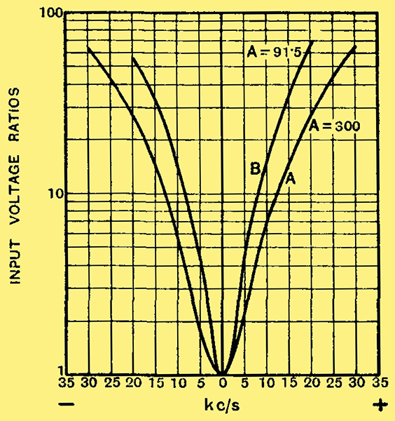
Fig. 5. - The results obtained with unscreened coils of 2,000 μH inductance with air-dielectric trimmers are shown here for two different degrees of coupling.
Owing to its comparatively low losses an air-dielectric trimming capacitor is desirable, but types at present available of suitably small dimensions have a capacity no more than 65 pF. For resonance at 465 kHz with this capacity an inductance of 2,000 μH is needed. Coils having this order of inductance and unscreened gave resonance curves of the type shown in Fig. 5 when used with a VMP4 valve and having only the load of a valve voltmeter on the secondary. Curve A is for the case of untapped coils with optimum coupling, and a stage gain as high as 300 times is obtainable. The curve is not quite symmetrical, for it gives an attenuation of 7.5 times at 10 kHz of resonance on one side as compared with six times on the other. The gain, however, is rather high for safety in a practical receiver in even one IF stage, and with two stages it would probably be impossible to maintain stability. It was reduced, therefore, by tapping down both primary and secondary, to 91.5 times, and the resonance curve then became B. A considerable improvement in selectivity is evident, for the attenuation at 10 kHz of tune now becomes 16 times and 14 times for the two sides, and it is very clear that the losses in the external circuit are playing an important part.
When an attempt was made to screen a transformer of this nature, however, many difficulties arose. Owing to the large field of the high-inductance coils, the screen considerably lowered the efficiency, and it also proved difficult to obtain sufficiently loose coupling between the two coils in a can of reasonable dimensions, while the physical dimensions of the air-dielectric trimmers added to the difficulties. Now experience had shown that it was possible to produce a considerably more efficient coil, although of lower dynamic resistance, if its inductance were lower, for in the given winding space it was possible to employ greater sectionalisation. A coil of 500 μH inductance was found to be about the optimum when wound with Litz wire in ten sections. It is out of the question with such a coil, however, to employ an air-dielectric trimmer, for the capacity required to tune it to resonance is some 300 pF.

Fig. 6. - The improvement in selectivity obtained by using low-inductance coils is well brought out by these curves.
The question arose, therefore, as to whether the more efficient coil would still be better if it were tuned with a mica-dielectric trimmer. The curves of Fig. 6 were consequently taken, and conclusively show that this is the case, the selectivity with the 500 μH coils being nearly double that with those of high inductance. Furthermore, on account of the smaller stray field, the losses introduced by screening are smaller, and less difficulty is experienced in obtaining loose enough coupling. The stage gain is lower, it is true, but this is an advantage rather than otherwise, and it does not fall as much as one would expect, since the external losses are of less importance, and one need not tap down the coils so far, if at all.
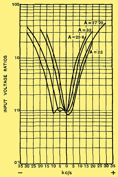
Fig. 7. - The results obtainable with a variable-selectivity transformer having excessive capacity coupling between the circuits. Note the lack of symmetry with tight coupling.
When the type of coil and trimming capacitor had been thus decided, the question of providing a variable coupling between two circuits arose. It was soon found that the coils had to be more widely separated when screened than when in air, due to the restriction of the stray field of the coils by the can causing an increased interlinking of the flux. In theory, coaxial mounting with one coil movable would be ideal, for it the low potential ends are placed towards one another capacity coupling is at a minimum. Experiment showed this to demand an excessively large can with the particular coils employed, and it was soon found that the best arrangement was to pivot one coil so that it could be rotated from a position nearly at right angles to the other towards parallelism with it. An experimental model on these lines with both trimmers placed at the top for convenience of adjustment gave the series of curves shown in Fig. 7 with a VMP4 valve. The anode of this valve was connected to a tapping on the primary coil so placed as to give a ratio of 3:5, and the valve voltmeter was joined to a secondary tapping giving a ratio of 5:2.
This series of curves exhibits two defects. In the first place, the amplification is rather low, for it never exceeds 32 times, and, secondly, the peaks do not open out symmetrically. This is a serious fault, and is due to the coupling not being wholly due to the mutual inductance, but partly to stray capacities. In order to avoid this it was found necessary to move the trimmers to opposite ends of the screening can and to bring the high potential leads out also at opposite ends. The use of a tapped secondary was also found unnecessary with these low inductance coils, and the use of the full winding for feeding the valve led to a considerable increase in amplification.
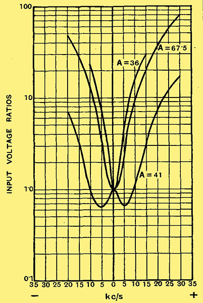
Fig. 8. - Symmetrical resonance curves are readily obtainable when capacity coupling is eliminated.
The results then obtained are shown in Fig. 8, and the gain at optimum coupling has jumped to 67.5 times, which is probably as much as can be used with safety in a two-stage amplifier. With the minimum coupling the gain is nearly half, but the selectivity is very good, the response at 110 kHz off resonance being 16 times down on one side of resonance and 22 times on the other. The slight lack of symmetry in this curve is due to the trimming not being perfectly accurate. With the tightest coupling the peak separation is about 10 kHz, and the curve is very nearly symmetrical. At this frequency the peaks are not so prominent that any real difficulty is felt in the low selectivity position of the control. It can be seen, however, that at 110 kHz the peaks would be very prominent and the trough between them excessive, so that a control of the circuit damping as well as of the coupling would seem to be essential. There are, of course, many possibilities, for several transformers will usually be employed together, and they need not all be controlled for selectivity. It seems likely that the best results will be secured by the combination of two transformers having variable coupling with one permanently set at optimum, or slightly above optimum, coupling. The precise arrangement adopted, however, will naturally vary in different cases, depending upon the results required, the number of transformers employed, and the external damping imposed upon them. It can be seen, however, that there is no essential difficulty in obtaining selectivity characteristics which can be varied over a wide range, provided that the intermediate frequency employed is not too low. The use of variable selectivity is likely to add very considerably to the performance of a receiver, particularly in quality of reproduction, and the importance of the development can hardly be over emphasised. It is likely to become widespread in the future.
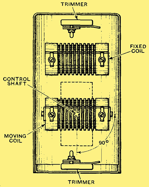
The principle of a variable-selectivity IF transformer is clearly shown in this skeleton drawing. The upper coil is fixed in position, but the lower can be rotated with respect to it by the control rod projecting through the screening can. Note that the trimmers are mounted at opposite ends of the screen to reduce unwanted capacity couplings.
|