|
The original on a B9 base it became the A15.
In the early days of broadcasting it was customary to use the same type of valve in every stage of a receiver. As design progressed, however, it was realised that different characteristics were needed if the varying functions of the different stages were to be carried out efficiently. This led to the multiplicity of valves which we know to-day and to a state in which it is not uncommon to find a different type of valve in every stage.
There is no doubt whatever that different stages in a receiver do require valves with different characteristics, but this does not necessarily mean that the valves themselves cannot be the same. A multi-electrode valve can be made to assumes wide variety of characteristics according to the potentials applied to the various electrodes and to the way in which they are connected.
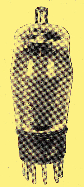
This principle has been adopted in the Harries All-Stage valve, which is so designed that it can be used in any stage of a normal receiver merely by connecting it appropriately, The valve is of the multi-electrode type having five grids and a critical distance anode. This factor of critically spacing the anode from the other electrodes is important not only because it increases the linearity of the characteristics and so reduces amplitude distortion, but also because it renders possible the construction of an efficient all-stage valve. Such a valve may be employed to perform the function of most existing valve types by suitably connecting the grids, and it will also permit the use of some circuit arrangements not possible with other types.
The valve is indirectly heated and consumes some 4 Watts; it is rated for maximum anode and screen potentials of 300 Volts and 250 Volts respectively. When connected as a frequency-changer a conversion conductance of 0.5 mA/V is obtained with an AC resistance of 1 MΩ. As a voltage amplifier for RF, IF or AF circuits the mutual conductance is 2.5 mA/V with an AC resistance of 1.2 MΩ and a grid-anode capacity of only 0.001 pF. Connected in this manner the valve takes an anode current of 5 mA, but when operated as an output valve it consumes 32 mA and has a mutual conductance of 5 mA/V. The valve may also be connected to function as a single-diode-triode or tetrode.
Improved AVG
One of the most interesting properties of the valve is in connection with AVC systems, for it enables many of the difficulties of present methods to be overcome. As Cocking has pointed out [★] The Design of AVC Systems The Wireless Engineer, August, September and October, 1934. Developing a Modern Quality Superheterodyne, The Wireless World, Feb. 14th, 1936. Is Automatic Volume Control Worth While? The Wireless World, May 22nd, 1936. See extras menu for links., the usual AVC systems are unsatisfactory and are really a compromise between cost and simplicity on the one hand and performance on the other. The ordinary systems are anything but distortionless.
The difficulties are overcome in the case of the All-Stage valve by applying the signal and the AVC voltages to different grids. In this way, linearity of characteristic can be retained while a very large change of mutual conductance for a given change in bias voltage can be secured.
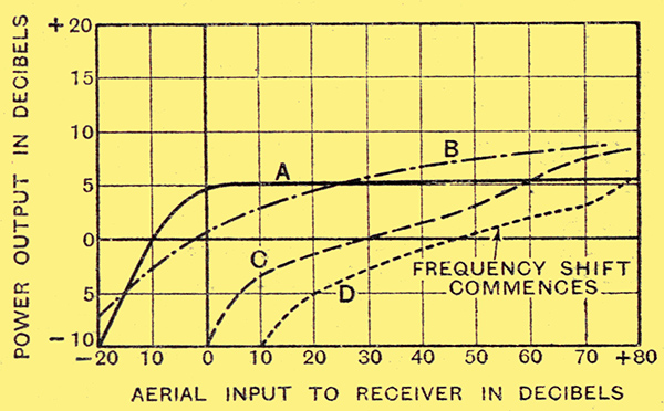
Fig. 1. The AVC characteristics of a superheterodyne embodying All-Stage valves are shown by curve A, while those of three typical receivers of ordinary type are illustrated by B, C, and D.
The AVC characteristic of a four-valve superheterodyne employing the All-Stage valves is shown by the solid-line curve of Fig. 1, while the results with three typical commercially produced receivers of today are illustrated-by the other curves. Not. only is the range of control greater, but the output is maintained at a more constant level.
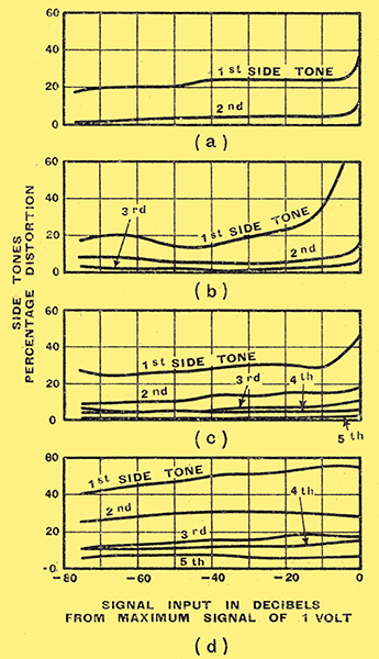
Fig. 2. The percentage side-tones introduced for the four receivers of Fig. 1 are shown here. The small amount of distortion introduced by the All-Stage valve is well brought out in (a).
The superiority of the new system is even more apparent when distortion is considered. The performance in this respect is indicated in Fig., 2, in which the overall distortion of the four receivers already mentioned is given. The method of measurement entails the use of a standard signal generator having itself a very low distortion level. Two different modulation frequencies are used simultaneously and the side tones caused by intermodulation are measured; it can be shown that this gives a much better measure of distortion than the usual procedure based upon harmonics of a single-frequency input.
When there are no side-tones, distortion is zero. Experience shows that 5% second side-tone is not serious, but larger amounts are audibly objectionable. Up to 20% or even 30% of the first side-tone can be tolerated, however, but very small amounts of side-tones higher than the second are serious, and coincide with harsh reproduction.
Bearing these figures in mind, it can easily be seen from Fig. 2 that the degree of distortion introduced by the receiver embodying the All-Stage valve is considerably lower than that with the others, and this is audible as an appreciable improvement in the quality of reproduction. Moreover, there is also an improvement in noise level and cross modulation.
At the time of writing, the valve is not yet generally available, but it is anticipated that it will shortly be marketed by the High Vacuum Valve Co., Ltd., in conjunction with whom the production model of the valve has been developed.
|