|
EL85Sensibly equivalent¶ to:
|
|
|
|
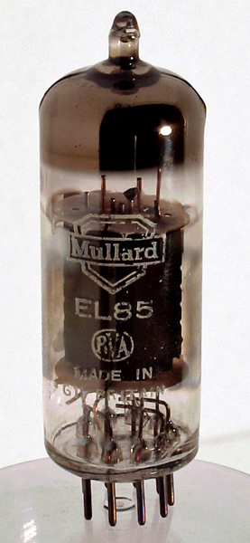
The EL85 appears to be the little brother of the EL84 pentode but is electrically identical to the B8A based EL42. When used for single ended audio applications a load resistance 9000 Ohms is specified. The original design purpose of the EL42 was for car radio output stages.The following is taken from a trade announcement in The Radio Constructor, March 1954. under the heading of - a versitile low current consumption miniature output pentode.Mullard Ltd. announce the availability of the EL85 AF and RF Output Pentode. This is a noval-based (B9A) valve intended for AC mains operation. The heater rating is 6.3V, 0.2A, which is low in view of the maximum cathode current rating of 35mA. The EL85, which has an anode dissipation of 6 Watts, may be used as an AF output valve or as an RF amplifier up to 120 Mc/s (MHz). As a Class A audio amplifier it gives an output of 2.8 Watts when operated with an HT supply of 225 V and an anode current of 26 mA. As an RF amplifier, it will deliver 2 Watts at 100 Mc/s.The EL85 should be of great use for equipments requiring moderate power out-put and where low LT drain is important. It is particularly suitable for mobile transmitters and receivers, where it may be used as a driver, modulator, or audio output valve.The thin glass tube envelope is 20 mm in diameter and, excluding the B9A base pins, is 58 mm tall.References: Data-sheet & 1040. Type EL85 was first introduced in 1954. See also 1954 adverts. |
Pin Connections
| 1 | 2 | 3 | 4 | 5 | 6 | 7 | 8 | 9 |  g1 | g1 | k | h | h | g3 | a | g3 | g2 |
|
|
Absolute Maximum Operating Conditions
| Vh | Ah | Va | Vs | Vg | mAa | mAs | ra | gm | Pout | D | 
| 6.3 | 0.2 | 225 | 225 | -10.8 | 26 | 41 | 90k | 3.2 | 2.8W | 12% |
|
Updated February 12, 2016.
|
|