|
EF8Sensibly equivalent¶ to:See also:
|
|
|
|
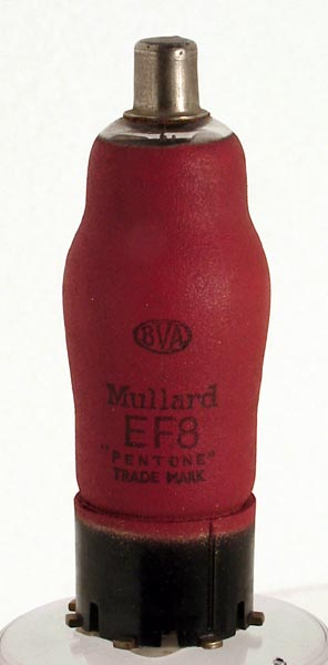
The EF8 valve is a variable μ amplifier pentode with a fourth grid.The variable μ amplifier pentode would be used in the AGC controlled stages of superhet receivers. The addition of the fourth grid suggests a possible use as a frequency changer, but this is not listed in the documentation.Our exhibit is unused, and has the distinctive red painted Mullard external metallisation screening.So what is the fourth grid really for? The valve is a true pentode device. Like all pentodes, it has a higher inherent noise than a triode. Much of this noise is caused by part of the electron stream departing from the cathode to anode current and leaving the valve via the screen grid.In the EF8, an additional grid was placed between the control grid and the screen grid. This grid was connected externally to the cathode and was wound with exactly the same pitch as the screen grid. Furthermore, the wires were exactly aligned with the wires of the screen grid. The screen grid had to operate at a higher voltage than normal (250 volts instead of the more normal 100-150 volts).The new grid and the screen grid between them formed a sort of lens that focused the electron stream into a beam, that projected between the screen grid wires, such that vastly more of the electrons missed the screen grid, resulting in a much lower screen grid current - and hence lower noise.One side effect of this mode of operation was that the screen was less effective than it would normally be and the grid to anode capacitance was higher than if the extra grid wasn't there. Around 2 to 3 times higher.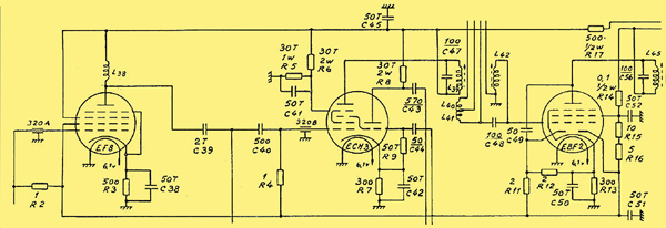
The image above (courtesy of Radiomuseum.org 3002) shows the circuit around the EF8 used in the Huldra 3 radio made by the Tandberg works in Norway between 1941 and 1946. The Huldra 3 was a luxury receiver. Thanks to Stig Comstedt for the information.This valve was designed for use as the first stage RF amplifier in something like a short wave receiver. It is likely from the fact that the construction didn't become standard in pentode designs that it was not as successful as Philips had hoped. Many thanks to Ian Sharrocks for this extra information.The classic envelope is 29 mm in diameter, and excluding the Ct8 base pins, is 84 mm tall.References: Data-sheet, 1040, 1043 & Ian Sharrocks. Type EF8 was first introduced in 1938. See also 1938 adverts. |
Pin Connections
| 1 | 2 | 3 | 4 | 5 | 6 | 7 | 8 | tc |  m | h | h | k | g4 | g2 | g3 | a | g1 |
|
|
Absolute Maximum Operating Conditions
| Vh | Ah | Va | Vs | Vg | mAa | mAs | ra | gm | 
| 6.3 | 0.2 | 250 | 250 | -2.5 | 8 | 0.25 | 2.0M | 1.8 |
|
Updated June 02, 2021.
|
|