|
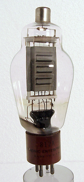
Type 812A is a variant of type 811 with a coarser grid and a lower μ of 29. This meant that the negative grid bias for Class C operation, and hence the RF input voltage, had to be increased but the overall result was slightly more efficient. A further variant (Type 812H) had an even heavier anode construction, allowing 85W dissipation and up to 225W of output when run at 1750V, 170 mA. However, this version was limited to 30 MHz and was thus in competition with numerous other HF types. Types 812/A/H were (and are) much less common than the original type 811.The anode box has channel sections added to form radiator fins. The grid is wide spaced and made from substantial gauge wire. This valve was used for low frequency RF power amplification or as an AF modulator.The filament is formed from Thoriated Tungsten wire and is formed into a pair of inverted V's. The top of the curves in the filament are held in tensioned hooks.The large classic envelope is 58 mm in diameter and, excluding the UX4 base pins, is 140 mm tall.References: Data-sheet, 3002 & 4038. Type 812A was first introduced in 1946. See also 1946 adverts. |
Pin Connections
| 1 | 2 | 3 | 4 | tc |  f | ic | g1 | f | a |
|
|
Absolute Maximum Operating Conditions
| Vh | Ah | Va | Vg | mAa | 
| 6.3 | 4.0 | 1250 | -40 | 175 |
|
Updated January 31, 2013.
|
|