|
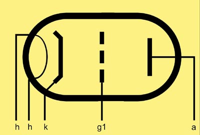
The triode was developed two years after Sir John Ambrose Fleming described a Diode as an Oscillation Valve. In 1906 Lee DeForest added a third electrode into the valve between the filament and the plate, this was shaped like a grid iron and he called the electrode the grid. He was trying to improve the sensitivity of radio detection by trying to control the flow of electrons between a heated (carbon) filament and a positively biased anode or plate. and the device produced he called an Audion. Today we know this configuration as the Triode.
The Audion was developed as a better detector of radio waves and DeForest had been working on flame detectors before modifying the Fleming diode. The Audion was a soft valve (i.e. not a hard vacuum) and was only used for detection in the years 1907 to 1913. Using the Audion for amplification was first demonstrated in 1912.
The first grid is called the control grid as its function is to provide a negative electric field and thus a barrier to the flow of electrons between the hot cathode and the anode. The first grids were not placed close to the filament. The hot wire filament sagged out of shape and the grid had to be kept clear. It was only later that it was discovered that the closer the control grid was placed to the cathode and the more closely the turns of the wire spiral to one another the more effect on the control of the electron stream it had. Over time the grid changed from the original grid iron shape through a helix of stiff wire supported on a support rod to a mechanically produced piece of precision engineering. Automated grid production centred on winding fine wire round two support rods. The machine would notch the (Nickel) support rod, lay the (Molybdenum) wire in the notch and finally burr the sides of the notch over the wire (known as peening) to lock it in place.
Knowing that the pitch of the grid wires was one element in the control of the electron stream grids with variable pitch were produced. These had close wound turns at the end and more widely spaced wires at the centre. This variable pitch grid is at the heart of the variable mu valves, where the sensitivity of the valve, and hence its amplification, can be altered by changing the amount of negative bias on the control grid.
The insertion of a grid between the cathode and the anode enables the electron flow to be controlled by applying a relatively small voltage to this third electrode. The power absorbed in the control-grid circuit is in many cases exceedingly small. By varying the potential of this grid the space charge can be modified in the same way as in a diode. The grid, because it is an open helix or mesh, does not present any mechanical obstruction to the electron flow, and as long as the potential on it is negative with respect to the cathode (or the negative end of the filament) it will attract no free electrons, but if it becomes positive, electrons will flow to it exactly as if it were an anode: when this occurs grid current will flow. In most valves grid current begins to appear a little before the negative bias reaches zero: this is due partly to the random movement of electrons as they pass the grid on their way to the anode and partly to the contact-potential differences associated with the materials used in the cathode and grid construction.
When it is necessary to ensure that the grid is always negative, the grid circuit must include a source of adequate negative voltage. This voltage, known as the grid bias, can be obtained in four ways:
- An independent source of fixed voltage.
- A resistor in the cathode lead.
- Grid current in a grid resistor.
- Contact potential.
In (a) the source of voltage may be a battery (usually dry-cells), or in transmitting equipment or high-power audio amplifiers it may be a mains-driven power unit. In (b) a resistor is connected in the cathode-to-earth lead of an indirectly heated valve or between the filament-supply centre-tap of a directly-heated valve and earth, and the total cathode current flowing through this resistor causes a voltage drop across it and hence the cathode becomes positive with respect to earth; if the grid return circuit is returned to earth the grid will be negative with respect to the cathode. The resistor is known as the automatic-bias resistor and the circuit arrangement as cathode bias.
In (c) if the valve is operated at such an amplitude that appreciable grid current flows and if the grid is connected to cathode and earth through a resistor, the flow of grid current will result in the grid becoming negative with respect to cathode. This form of grid bias is employed in oscillators, frequency multipliers and class C amplifiers and is known as grid-leak bias.
In (d) the grid is connected to the cathode through a high-a value resistor (usually 1-10 Megohms) and the flow of a small a amount of grid current will bias the grid to almost the contact potential. This form of grid bias is suitable only for small a valves having very small signal input voltages. If the grid potential is varied, the anode current will vary in a corresponding manner; further, if a resistance is connected in the anode circuit, the voltage drop across it will vary also in the same way. If this resistance has a suitable value the variation of voltage drop will be of greater amplitude than the variation of grid voltage; hence the ability of the triode valve to amplify.
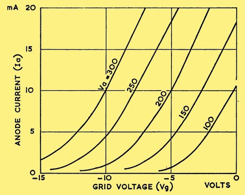
If the relationship between the variation in grid voltage and the change in anode current is plotted graphically, the resultant graph is known as a characteristic curve. A series of such curves may be plotted with different anode voltages: the set of curves is known as the anode-current/grid-voltage characteristics (la/Vg).
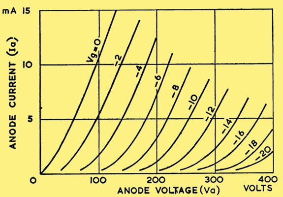
A second series of curves may be plotted for anode current versus anode voltage for a series of different grid voltages. These are known as the anode-current/anode-voltage characteristics (Ia/Va).
|