The 6M11 has two high μ triodes and a sharp cut-off pentode. The maximum anode volts are over 300 but the design operating value is with 125 Volts on the anodes as the main use was in television receivers. The data-sheet has full operating details.
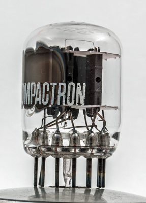
At this angle the ends of the two triode sections are visible.
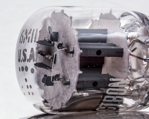
Here one of the triodes is on the left with the pentode on the right. The strap connects the two sides of the anode and the dark box inside the strap is the beam forming plate. The pentode cathode is a flat box shape and the control grid is wound on copper supports. The pentode has a gm of 13.0 but the control grid does not appear to be of frame grid construction.
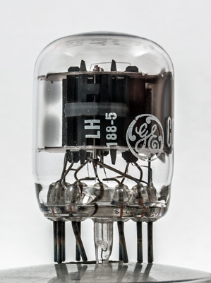
The General Electric logo with the screen grid visible below the letters LH.
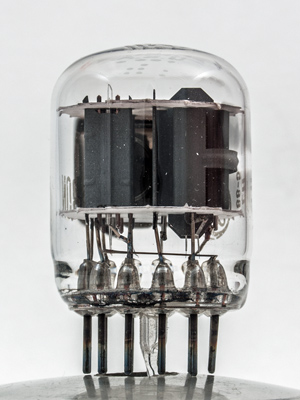
The dome carries the Type designation and the country of origin. The twin triode anodes are clearly seen as are their copper grid supports.
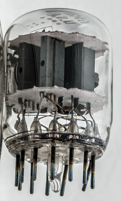
The view below the bottom mica. The pentode heater is connected across the heater bus-bars and the triode heaters are run in series across the 6.3 Volt line.
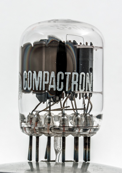
The wide glass tube envelope is 28 mm in diameter, and excluding the B12C base pins is 37 mm tall.
Reference: Data-sheet. Type 6M11 was first introduced in 1962. See also1962 adverts.