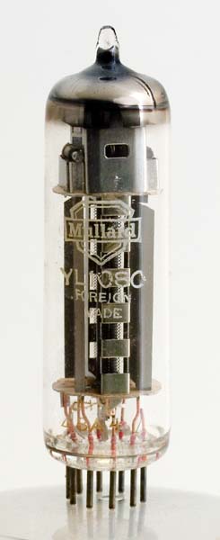
The YL1080 is a quick heating version of the QQV03-10 VHF transmitting double tetrode. This valve is designed to operate in the VHF frequency range 67-200 MHz. Designed for oscillator, multiplier or PA service it was planned that this valve would operate in class C. The anode dissipation is 4 Watts per anode and an RF output power of up to 12 Watts was possible.
The valve follows the european pattern with internal neutralisation and separate anodes either side of a common cathode core.
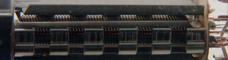
The control grids are independent but the screen grid and beam plates are common. In this picture the beam plates are wider than the treated anodes. The oxide coated filament is formed from wire that is formed into a long flat coil that passes vertically through the valve. At the top is a strong spring to maintain filament tension between hot and cold states.
Looking into the anode cavity the bright beam forming plates show as a rectangular opening that reveals the grids. The screen grid can be seen as formed so as to pass flat in front of the cathode.
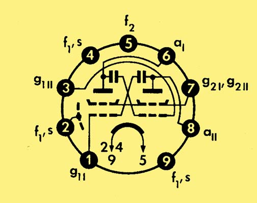
The diagram of the electrodes shows the built-in capacitors for neutralisation. By neutralisation the valve is able to operate without breaking into parasitic oscillations.
The thin glass tube envelope is 20 mm in diameter and, excluding the B9A base pins, is 68 mm tall.
Reference: Data-sheet. Type YL1080 was first introduced in 1960. See also1960 adverts.