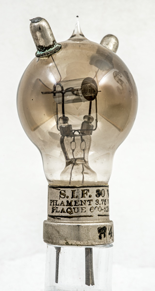
This SIF horned transmitting valve probably dates from the early 1920s. The two top cap connections were present to allow higher frequency working. The anode dissipation is given as 30 Watts on the base cap. See alsoHorned and NR8.
While pumping the envelope the anode would be held at high potential and filament run to allow electron bombardment to heat the anode. The nickel at high temperature would out gas and any impurities in the metal would be deposited on the glass as appears to be the case with this exhibit.
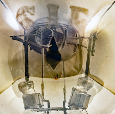
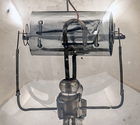
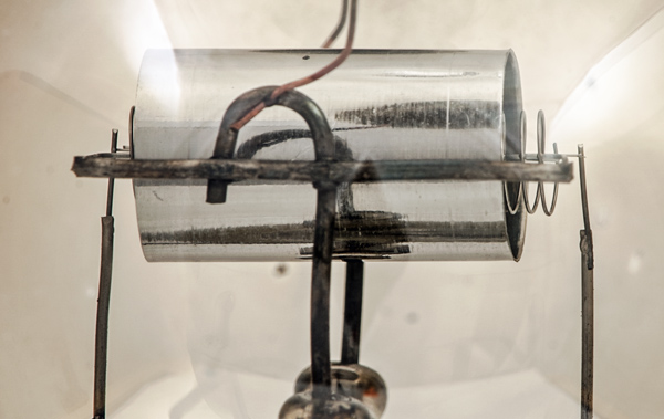
The construction of the triode is conventional for the period, being co-axial. The anode cylinder contains a helical wire grid supported at both ends and both sides, and running through the centre of the anode is a single strand tungsten filament.
Thanks to Mike Barker for the loan of this valve.
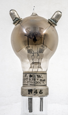
The SIF on the glass and the valve ratings on the base cap.
This enhanced image shows the etched lettering and the co-axial construction.
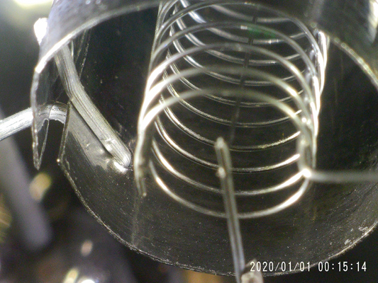
The grid is held at each end and the individual turns of the helical grid are welded to a support wire. The filament is a single strand. The anode cylinder is held closed by the support wires threaded through holes and bent over.
The electrodes from the image above.
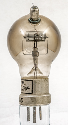
Here the filament can be seen to be welded to the support rather than held in a fold of the support wire. This suggests that the filament may not be tungsten or that the melting of the support wire is the method of fixing.
The grid with central filament. The anode support on the left shows the fixing method.
Thanks to Mike Barker for the loan of this valve.
The balloon envelope is 55 mm in diameter and, excluding the B4 base pins, is 96 mm tall.
Reference: 1003 & private communication. Type Horned was first introduced in 1916. See also1916 adverts.