|
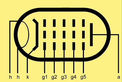
The heptode has five grids and was developed as a mixer valve. Within the single electron stream from cathode to anode the first two grids form the local oscillator. The control grid is of conventional design but the second grid would be typically just two support rods as it was to function as the anode for the oscillator. The local oscillator introduced an electrode stream of varying amplitude into the remaining grids. Grid three and grid five both acted as screen grids to provide signal isolation. Between them would be a second control grid, grid four, that would be the input point for the signal. For maximum isolation grid four would often be taken to the top cap.
The oscillator, mixer and amplifier functions all take place in the same electron stream so a high degree of coupling between them is inevitable. One result is that the oscillator frequency 'pulls' strongly in favour of powerful signals and away from weaker ones. For receivers intended to receive strong local signals only this could be sold as an advantage as they were 'easy tune'. Another consequence is that the oscillator frequency is coupled to the signal input grid and will leak out of the aerial unless an efficient tuned filter is interposed. A further problem is that it is difficult to apply AGC to a pentagrid without adversely affecting oscillator performance.
Despite these disadvantages heptode frequency changers, or Pentagrid Converters, remained the norm for many years in low-consumption battery portables which were only intended to receive strong local stations and where their economy of current drain (only one filament, only one electron stream) was of vital importance. This was mainly in Europe. The USA was moving in the direction of the superhet receiver and the addition of AGC to the mixer was important.
The heptode suited Medium and Long-wave receivers but not Short-wave receivers. To provide a solution to Short-wave superhet reception the triode hexode was developed.
|