|
Short CRTs bring new problems in TV set design.
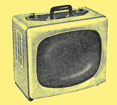
The Pye PV110 l7-inch transportable receiver with 110° cathode-ray tube.
The first of the long-awaited 110° television sets has now arrived on the British market - a 17-inch transportable made by Pye. As can be seen from the illustrations, the use of a 110° CRT achieves a considerable reduction in cabinet depth, and in fact this dimension is only 13¼ inches overall (the height being 15 inches and width 17½ inches).
In general the 17-inch tube with a 110° deflection angle is about 3 inches shorter than the equivalent tube with a 90° angle. This particular CRT is the C17/6A made by Cathodeon, a subsidiary of Pye. It has a rectangular screen of 5:4 aspect ratio (slightly increasing the picture area over 4:3 tubes but cutting the picture sides a little) and a narrow neck of 1⅛in diameter which makes possible the greater deflection sensitivity required to scan the 110° angle. The electron gun is a tetrode type with an electrostatic focusing electrode, and the final anode operates at 16 kV. It is a straight gun and no ion trap is required. At present the 6.3V tube heater takes a current of 0.6A, which means that it cannot be included in the series heater chain and a special transformer has to be provided. In later models of the set a series-heater tube will be used.
Conforming to the modern tendency with transportable receivers, the cabinet plays a very minor role in the construction of the set. It is merely a decorative cover enclosing the metal frame into which the set is built. A moulded plastic mask-cum-filter-screen covers the front of the tube, giving protection and improving the picture contrast when room lighting is on.
The two main problems in the design of such 110° receivers are (a) obtaining sufficient scanning power to deflect the CRT electron beam through the wider angle, and (b) getting the circuitry into the reduced space resulting from the use of the shorter tube. Taking the electrical problem (a) first, this is a matter necessitating very careful design of the line and frame output stages, transformers and deflection coils. A PL81 valve is used for the line output and a PL84 for the frame output. Several improvements in the line output transformer are obtained by a technique known as 'DC cancellation' applied to the ferrite core. The direct-current anode supply to the line output valve passes through a section of the transformer winding in the normal manner but it also has to pass through another section of winding in the opposite direction. The magnetic fields produced by the DC in the two sections therefore tend to cancel, and this reduces the magnetic loading on the core.
Apart from slightly increasing the transformer efficiency, this technique largely eliminates the timebase whistle which would otherwise be extremely annoying in such a high power scanning system. The transformer leakage inductance is tuned on the 'third harmonic' principle, which, as well as mitigating line scan ringing, reduces the peak voltage on the line output valve and PY81 efficiency diode and so leads to higher efficiency by allowing higher turns ratios.
The anode load of the PL8l line output valve is arranged so that the anode is driven hard into the 'knee' of the anode voltage current characteristic. This, in conjunction with a carefully chosen screen grid resistor, makes the scan amplitude largely independent of the valves characteristics. Moreover the amplitude does not change appreciably with reasonable mains voltage variations. There is no line scan amplitude control as this is considered a source of wastage of scan power.
In the frame scan output stage improved efficiency in the output transformer is obtained by the use of a grain-oriented low-loss steel for the core laminations (called Unisil and made by The Steel Company of Wales).
The deflector coil assembly is characterised by a pronounced flare at one end of the windings, which allows the coils to extend a good distance up the cone of the tube. This is done so that the centre of deflection of the assembly can be as close to the screen as is necessary to avoid interruption of the beam by the end of the tube neck at the extremities of the 110° scan. Another reason for extending the windings as far as possible up the cone is to lengthen the distance in which the electron beam is affected by the magnetic field and so reduce the scanning current requirements. The coils extend as far back in the other direction as is practicable in a short-neck tube, and even overlap the final anode cylinder slightly.
The so-called 'cosine' distribution of winding cross-section is used on the deflection coils to give uniformity of focusing all over the screen (which, of course, is particularly difficult to obtain with large deflection angles). This technique is well known for producing slight concavities in the sides of the raster ('pincushion' distortion) but correction is applied by small permanent magnets attached to the assembly. Toroidal frame coils are used, and thermistors are connected in series and incorporated in the assembly to correct the resistance changes caused by heating which would otherwise affect the picture height.
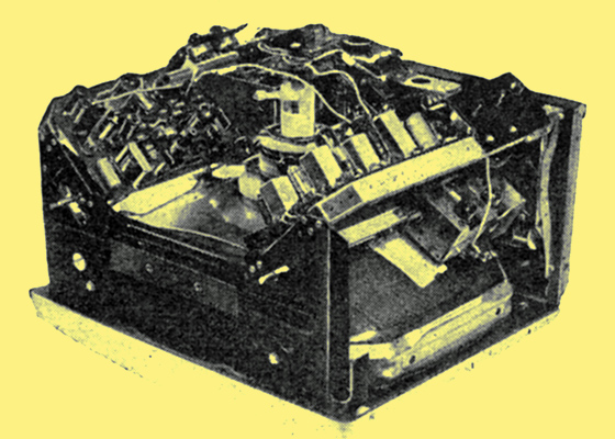
Back view of the Pye receiver with cabinet removed, showing how the tuner unit is mounted and the easy accessibility to the printed circuit boards.
On the question of mechanical design, the main problem, as mentioned earlier, has been to find sufficient space for the circuitry around the short neck of the tube. Transistors are the obvious answer but this is a thing for the future. Meanwhile Pyes have worked out a neat form of construction based on two vertical printed-circuit panels on each side of the neck. When the cover is removed from the set both sides of these can be reached easily for servicing purposes. Power and EHT supplies are arranged separately at the bottom of the chassis.
One of the largest circuit sub-assemblies in any television set is the tuner unit. Here the designers have saved a great deal of space by introducing a new miniature incremental inductance tuner (made by HDF, Ltd., of Lowestoft) which measures only 3½in x 2½in x 2½in. It is situated between the back of the signal-frequency printed circuit and the tube cone. The four rotating coil switching wafers are of small diameter (actually 1¼in) and the coils are mounted on them and rotate with them (as distinct from previous Pye incremental inductance tuners in which the coils were connected to the fixed contacts of conventional wafer switches). Some of the Band III inductance increments are just formed by conductors joining the switch contacts and are fabricated by printed circuit technique. The tuner circuit is the widely accepted arrangement of PCC84 cascode RF amplifier and PCF80 mixer/oscillator.
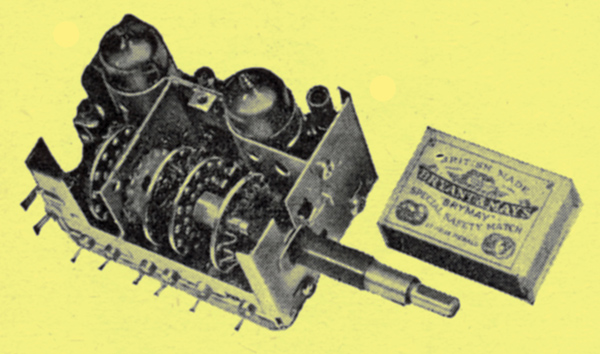
The incremental inductance tuner of the Pye set, with cover removed to show the small switch wafers with coils mounted on them.
|