|

Experimental version of the VT90 the original micropup.
Common-anode Earthed-anode Oscillator Valves
Construction

Diagram of the NT99 in section.
The general form of construction adopted for transmitting valves of this class is shown above. It consists of an outer cylindrical anode with fins attached for air cooling. This copper anode forms part of the envelope, and to each end of it is sealed a short length of glass tubing. The grid is rigidly mounted on a glass-metal seal at one end, and the filament or cathode is supported from the other end. The construction gives a geometrical arrangement which is suitable for use with coaxial lines.
History
The first valve designed along these lines specifically for pulse operation was made in 1939; it was known as the "Micropup", and later as the VT90. Valves for pulse operation must withstand a high anode voltage and pass a large anode current during the pulse, which is usually of a few microseconds duration. However. since the off-period/on-period ratio is usually greater than 500 : 1, the mean dissipation at the electrodes is small.
The micropup in its original form operated at frequencies up to 600 MHz. The upper limit of frequency of the VT90 itself, however, was limited to about 300 MHz, because the length of glass between the anode and grid seals had to be great enough to avoid flash-over at high altitudes when used at the full anode voltage in airborne equipment.
To increase the power output from this class of valve without simultaneously reducing its maximum frequency, the principle of radial enlargement was adopted. Thus, by increasing the diameter of the electrodes whilst keeping their lengths and spacings the same, a series of valves of ever increasing output was developed. In this way, the power output at 600 MHz was increased from about 5 kW given by a pair of the original micropups to some 400 kW given by a pair of the largest experimental valves of the series. All these valves were used in concentric line circuits, and care had to be taken to arrange that the electrodes, particularly the grid and anode, and their seals formed a smooth continuation of the external circuit without any abrupt change in characteristic impedance. The inter-electrode capacitances increased with the radius, and the characteristic impedance of the tuned lines had therefore to be reduced. This was important from the point of view of grid-seal design.
Anodes
The anode design remained unaltered throughout the whole of the micropup series. It consists of a short length of copper tube, flared and feather-edged at both ends. The active portion varies in diameter from 0.5 in in the smallest valve to 2 in in the largest. The copper-glass seals present no difficulty but the glass must completely enclose the sharp edge of the copper otherwise there is danger of discharge from this edge at the high anode voltages employed. The glass is a standard boro-silicate glass having a coefficient of linear expansion of 3.7 × 10⁻⁶/°C.
Grids
In valves for pulse operation, where the mean power is usually small, grid emission does not present such a serious problem as in valves for CW use. Nevertheless, avoidance of grid emission is an important factor in grid design, particularly in valves with oxide coated cathodes, where the operating grid temperature must not appreciably exceed 300 °C if grid emission is to be avoided. In the types of valve under consideration, cooling of the grid by thermal conduction has been found to be the best method of achieving this result. The alternative of cooling by radiation is often impracticable, because of the large surface area required to radiate the energy at such a low temperature; this would increase capacitances and would load the lines, thereby reducing the maximum frequency of operation.
When the grid is cooled by conduction, it must be in good thermal contact with its support or seal member, which in turn must be able to conduct the heat to the outside of the envelope where it can be removed, e.g. by a stream of air. It is also necessary for the grid wires themselves to be as short and thick as possible.
These considerations led to the adoption of the "squirrel cage" form of grid, consisting of a number of wires uniformly spaced around a cylinder, and attached to a narrow ring at the open end and to a shallow dish at the closed end. The grid wires are usually of molybdenum, because of its relatively high thermal conductivity and good mechanical properties. but the end ring and dish may be of nickel for ease of spot welding.
Grids of tantalum wire can sometimes be used to advantage in valves with thoriated-tungsten filaments. The gettering action of tantalum when properly pre-treated is useful, and the fact that the thermal conductivity is lower than for molybdenum is unimportant, since the temperature for the onset of grid emission is so much higher with the thoriated tungsten filament.
In most of the valves, the grid is designed for an amplification factor of the order of 20. To avoid a long tail in the characteristics, it is desirable that the spacing between grid wires should not exceed the grid-cathode distance; the latter is determined by transit time considerations, and it is therefore often necessary to effect a compromise between the conflicting requirements of good thermal conductivity and good electrical characteristics.
In the smaller grids, the wire diameter is 0.05 mm.
Filaments and Cathodes
Filaments of thoriated-tungsten wire were used in the early valves. The filament in the VT90 consisted of a single helix of thoriated-tungsten wire, 0.35 mm in diameter. Its rating was 8.25 volts, 7 Amp, and it gave a peak emission of more than 5 Amp. The radial enlargement principle mentioned earlier depends on the use of a larger filament to yield more power.
As the diameter of the filament spiral is increased, so the tendency to sag becomes greater. The stability of these larger diameter filaments was improved by using thicker wire and by reducing the length of wire in the spiral. The total filament area was increased by using a double instead of a single helix, which was possible because of the increased pitch. However, this type of filament could clearly not be enlarged indefinitely, and other forms had to he explored. A satisfactory construction, which was used in large numbers of experimental valves, consisted of a number of limbs, made in the form of zig-zags, uniformly spaced around a cylinder. The largest filament structure of this type was 20 mm long and 35 mm in diameter; it consumed 700 Watts and gave an emission of over 100 Amp.
At about this time, experimental pulse valves were being made with oxide-coated cathodes, in order to increase the emission still further. It was found that pulse-operating conditions were conductive to emission maintenance; in fact it was usual for the cathode emission to increase during operation. A change in operational technique was necessary, however, before valves with oxide-coated cathodes could be introduced. The thoriated filament valves, being capable of withstanding high DC anode potentials, were usually grid-modulated in operation. Those with oxide-coated cathodes, however, would not withstand such high voltages because of their tendency to flash-arc, and it was therefore necessary to anode-modulate them. Application of anode voltage in pulses of a few microseconds duration does not allow time for the flash arc to build up, and it is possible in this way to operate the oxide-coated valves at at least as high an anode voltage as their thoriated-tungsten counterparts.
When the oxide-coated cathode technique was proved by life tests to be satisfactory and reliable, several types of valve were designed to meet service needs and to replace thoriated-filament valves already being developed.
In chronological order, these were the CV55, NT99, and CV240. Of these, the NT99, which is intermediate in size, has been the most widely used. Its cathode consists of a circular nickel cylinder, closed at both ends and heated by a central tungsten spiral. Only the cylindrical surface of the cathode is coated; the coated area is 8 cm2, and the rejection emission limit is 40 Amp. The cathodes in the other valves are similar in design and differ only in size.
Assembly
The same method of assembly is used for all the valves in this series. The final sealing operation in which a glass-glass joint has to be made whilst holding the cathode central within the grid may call for the highest accuracy. In the larger valves, where the grid-cathode clearance is of the order of one millimetre, the problem is not so difficult, but a very high degree of precision is necessary for example in the CV55, in which the clearance between the cathode coating and the inside of the grid wires is 0.15 mm.
The main steps in the assembly process are as follows. First, the anode and grid seals are glassed; this is done in a miniature glass lathe which ensures accuracy of alignment. Next, the glassed grid seal is sealed to one of the glass tubes. The grid seal must be accurately disposed with respect to the anode, both axially and radially, and this is assured by the use of suitable jigs. The metal-glass envelope is now complete. After chemical cleaning, the grid is fixed in position by screwing to the grid seal through a small hole in the centre of the dish at the closed end of the grid. There is no adjustment in this operation, hence the need for accuracy in sealing the grid seal to the envelope. The final operation is the sealing of the filament or cathode-heater assembly into the glass tube on the end of the anode remote from the grid seal. The filament or cathode-heater system is first mounted on two tungsten wires which pass through a glass button, or small flared pinch. The button is preferred because the glass does not project towards the hot region of the valve, and is therefore cooler. The method successfully adopted for holding the cathode accurately central within the grid during the sealing is shown below.

Each component is mounted on the end of an accurately-ground steel mandrel C, both mandrels being of the same diameter. The glass-metal envelope containing the grid is mounted on its mandrel by means of the grid-seal. The cathode system is held by gripping the short tungsten support wires in a special clamp D. The cathode and grid are then adjusted by means of the screws S to lie accurately along the axis of their mandrels, an optical method being used to carry out this adjustment.
The two mandrels are then clamped in two V-grooves which have previously been scraped to give accurate alignment on a test-bar. The cathode is then gently inserted into the grid until it reaches the correct axial position, when the mandrel is clamped. The whole is then hung vertically, and the glass button is sealed to the glass tube without rotation by means of an oxy-coal-gas hand torch.
Performance
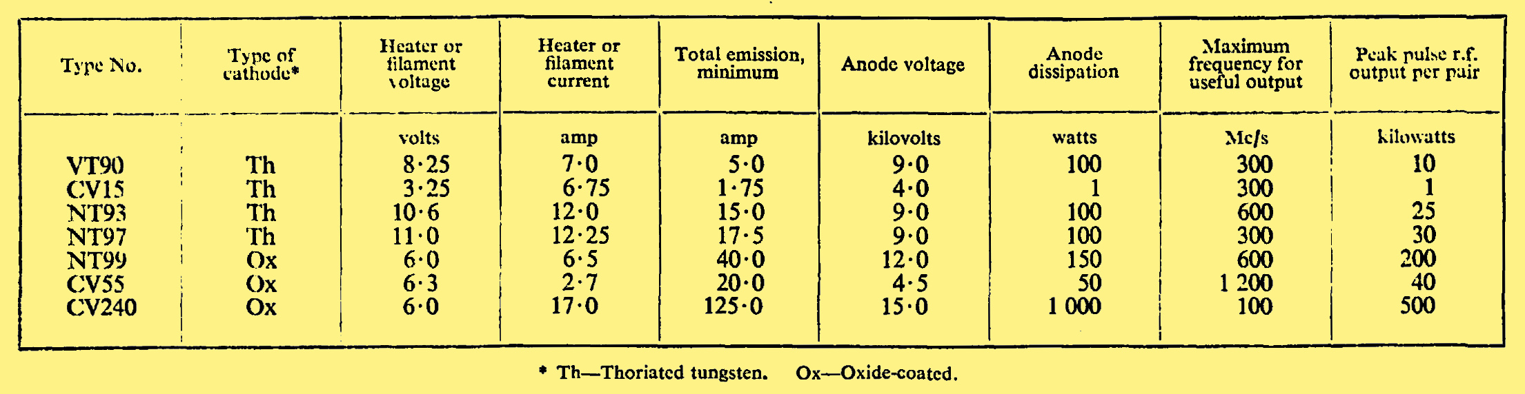
The performance under pulsed conditions of the various valves in this series is shown in the table below. Only those types used in service equipment are included.

See also The First Airborne Radar & W5534.
|