Valve manufacture in the UK was a large industrial operation in the 1950s with millions of valves being produced each year. The plants were large and the processes very labour intensive by today's standards. One of the most prolific of the valves of the time was the MullardEF80. This pentode was used in Intermediate Frequency amplifiers for many types of equipment: radio, Radar but probably best known as the dominant workhorse of VHF television receivers.
Mullard made promotional material about its valve manufacture that included both a presentation box of EF80 components and a film showing the manufacture of the valve. This film and the box of components has been the basis for this article. The British Vintage Wireless Society has made a DVD of this film available to members. It is a wonderful piece of industrial and social history.
Press ▷ above to play. If the film does not play, join as a friend here
The Mullard film on the making of the EF80.
The boxed set of parts can be seen below. Some of the parts have oxidised with age and this can be especially seen with the control grid. The film talks of all grids being fabricated from molybdenum but in the box set the control grid is clearly made from copper. The hypertext links allow for detailed footnotes about the processes to be included without making the main narrative too long.
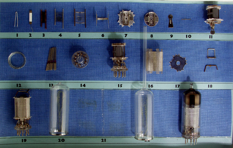
The heater is a V shaped component that looks deceptively simple. In practice the tungsten wire used to make the filament is 7 μm in diameter and fragile. When forming the heater, the wire is wound on a molybdenum rod mandrel that is subsequently dissolved away in acid. The heater helix is formed into the hairpin shape and dipped in an alumina insulating coating that is dried by passing current through the heater wire itself.
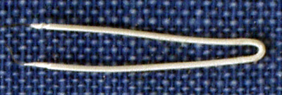
The cathode is formed from a flat nickel tube. Once formed to size the cathode tubes were sprayed with a mixture of barium and strontium carbonates. These carbonates are reduced to the working emissive coating during the final pumping process.
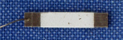
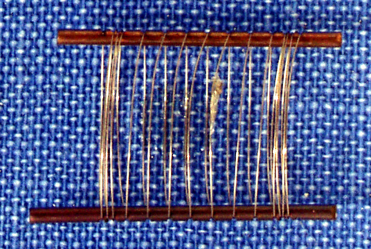
The control grid seen above is made from copper although molybdenum wire was also used for control grid manufacture. The first stage process involved winding long lengths of grids in a wire wrapping machine. The machine would notch the support wire rods with a sharp circular knife. Into this notch was then immediately laid the grid wire under tension. The notch process would generate a ridge either side of the cut and the final act to secure the grid wire in the notch was to roll over these ridges with a peening roller. This squashed the displaced material back into the notch and fixed the grid wire in place. Between one grid and the next the wire spacing was greatly enlarged. The individual grids were later cut from the large lengths manufactured. After cutting to individual pieces the grids would be hand fed onto shaping jigs that would stretch the grid wires and form the final shape.
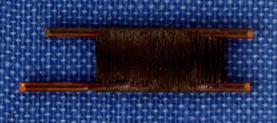
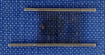
The screen grid (above) and suppressor grid (below) are both formed by the same manufacturing process as the control grid. The wire is molybdenum but the gauge is selected to suit the intended function.
In the picture of the suppressor grid the notches in the copper support wires can be clearly seen.
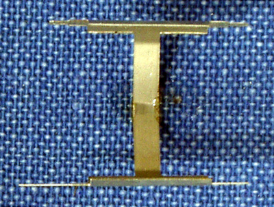
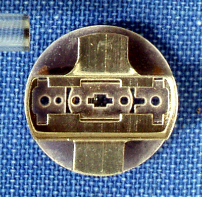
For small receiving valves like the EF80 the anodes were made of nickel sheet that was stamped, formed and any seams made and closed on a single machine. The EF80 is a low power device and the anode has two collecting flat sections that are held in place by the joining strap. In the view shown the joining strap is visible with the flat portions facing away from the camera at the top and bottom of the image. Note also the small retaining lugs at the corners of the finished assembly.
In the EF80 the various components are held in place by insulating mica sheets. The mica shown above has also had support metal work added. This may also be used for cooling by radiation.
The other mica support and shield is pictured here. The object at the top left of the picture is the end of the pumping tube.
The tiny pieces of matal seen above are used as radiators and fixings.
To assemble the previous components into the finished form took great dexterity, tweezers and a small support jig. The EF80 assembly started with the bottom mica into which was located the cathode. The grids were placed over the cathode in order from g1 to g3 before the anode was carefully placed in the bottom mica. The top mica was then placed and the electrodes moved about with the tweezers until all the protrusions passed through the top mica.
The workers were normally women and although not mentioned in the film high production speeds were probably encouraged by paying the women piecework. Essentially money was only earned for each successfully completed unit of production and the faster workers would earn the most money. These practices are far less common in the UK today. Also piecework was popular before the days when repetitive strain injury was a recognised problem. In the picture can be seen one of the main collecting surfaces of the anode. The surface looks grey and is due to the treatment applied to make it a better radiator of heat than the bright original nickel sheet would have been.
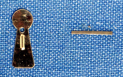
An all glass valve often looks as if the glass is formed in one piece but this is not the case. The base and envelope are made from different types of glass and are fused together during production. Shown above is a short section of hard glass tube that will form the pressed glass foot or base.
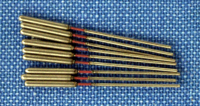
Base pins are another area where the complexities of manufacture are rarely considered. The pin that enters the socket has to be firm but not hard and brittle, the section that passes through the glass has to stick to the glass and expand with temperature at the same rate as the glass to avoid breaking the seal. Finally, inside the envelope, the wire has to be easily shaped to marry up with the lower end of the main electrodes. The base pins seen here are made from three different types of metal. The short centre section is called red Platinum after the fact that early valves used Platinum itself, but is in reality a special alloy.
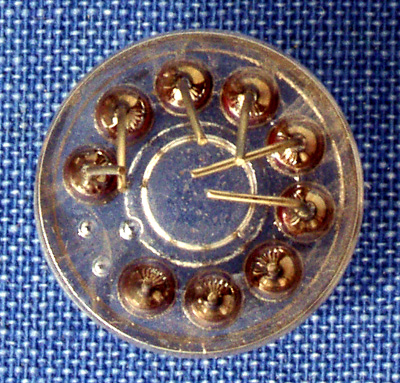
The picture shows the final base. The pins are inserted by machine nine at a time into the base forming jig. The hard glass tube is fed onto the top of the pin jig and heated in a gas flame until molten. A rotating toothed wheel keeps the glass in place. The next stage of formation is to enclose the molten glass by a tube raised from below and to press down from above by a second shape forming die.
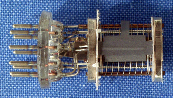
The base and electrodes are manually placed in another specially constructed jig so that the base wires can be spot welded to the lower ends of the electrode supports.
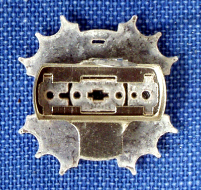
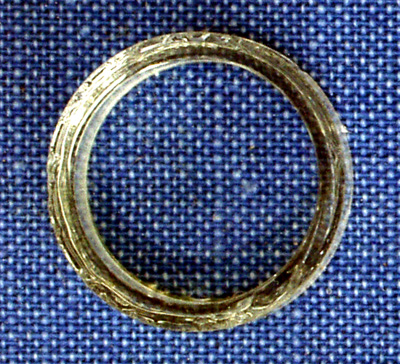
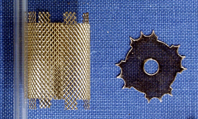
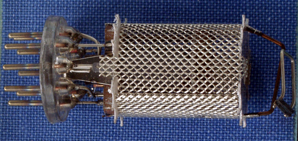
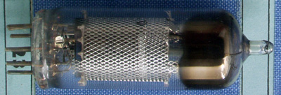
The pressed mesh is the electrostatic screen used to shield the workings of the valve from external fields. The small lugs on the mesh will be folded over by hand held tweezers to hold the top mica. This mica is shaped to be a tight fit in the glass envelope and allows the electrodes to be rigidly held in place in the final valve.
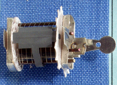
A further support wire is added in the last production jig and spot welded into place. The getter shown in the picture as a white rod at the left end of the bright wire support.
The final assembly has the getter at the extreme right of the picture. The main electrodes are hidden by the supports from the getter. This is to ensure that when the getter is activated the volatile materials condense on the envelope and not on the grids and anode.
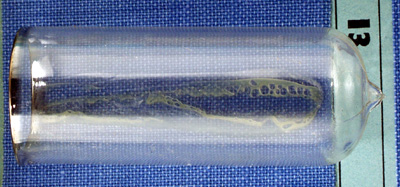
The soft glass tube for the envelope is cut to size. The base end is heated and flared out. The top end is heated strongly in gas jets to melt the glass. Once molten the glass is pressed to form the dome and pip.
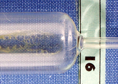
Another tube of glass has to be added to the envelope tube. This is the pumping tube and after being cut to length it is raised up to the pip at the same time as a minute gas jet is introduced through the envelope tube from the top. The two tubes are fused to form the composite glass envelope.
The final pumping and testing stages fuse the base to the envelope, drive out occluded gasses, form a high vacuum and finally seal the envelope.
After the envelope is sealed and as part of the testing regime the cathode is finally conditioned to optimise the working conditions. The now finished valve is inspected and subjected to a further battery of tests to ensure compliance with the specifications and tolerances of the published design before being printed with its identifying markings and packaged for sale.
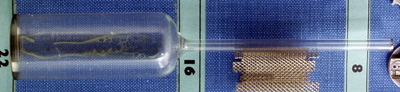
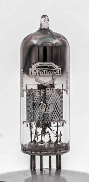
The EF80 as a finished item clearly shows the dark inside of the top of the envelope where the getter chemicals coalesced after firing and trapped with them on the glass surface the final traces of gas left after pumping.