-
Contents
(Within the text click a heading to return here)
- A Ceiling at 30 MHz
- Get Small to Go Fast
- Blacklisted Acorns
- The Challenge of Television
- RDF (RADAR)
- The Return of the Redcoat
- Flight from Holland
- The Pye 45 MHz IF Strip
- Acknowledgements
- Additional Comments
By the early 1930's screen grid and pentode valves were available for RF amplification for frequencies up to about 30 MHz, which was adequate for both broadcast and commercial purposes at the time, when radio usage had not extended into the UHF band. At frequencies above 30 MHz the gain available from valves fell very sharply; there were two principal problems: the first was caused by the inductance and capacitance of the internal leads that connected the valve electrodes to the terminating pins; the second was due to the finite transit time that the electrons took to travel between the valve electrodes.
The first problem arose through the valve design and manufacturing techniques which had evolved from those used in the electric lamp industry. One particular constructional feature of the valve, copied directly from the lamp industry, was the use of an internal glass stem and pinch that held the support wires to the electrode assembly, and also provided a vacuum seal for the lead-out wires. The problem that arose from this method of construction was that the total length of the connections from the electrodes to their terminating pins was quite long, resulting in significant self-inductance of the wires as well as excessive self-capacitance between them. At frequencies below 30 MHz, these parasitic inductive and capacitive components did not seriously affect the performance of the valve, but their effects became increasingly more serious at frequencies above this.
The second problem - the finite transit time for the electrons to move between the electrodes - was very serious for valve circuits operating at frequencies above 30 MHz. For a typical RF valve of conventional construction, the transit time for the electrons to move between the cathode and control grid was about one nanosecond (one thousand-millionth of a second). At frequencies of a few megahertz, this transit time was insignificant compared with the time for one cycle of the signal frequency. At 100 MHz, however, the time was about 10% of one cycle and this was very significant. The phase lag caused by this time delay resulted in a low input resistance at high frequencies, which significantly reduced the amplification available.
A great deal of experimental research work was carried out at the RCA laboratories during the early 1930's to investigate the behaviour of radio frequency amplifier valves, where it was found that improved circuit performance could be achieved if the valve dimensions were reduced. With a linear reduction, the mutual conductance and other valve parameters remained almost unchanged, but the lead inductance, inter-electrode capacitance and electron transit time all fell in direct proportion to the reduction of dimensions. In fact, such a linear reduction was not practical; however, the tiny 'Acorn' valves that resulted from this work were capable of providing amplification at frequencies up to about 400 MHz. See also 956 Data Sheet
The first of these valves to go into production was the type 955 triode which was introduced in 1934. This was followed by the 954 pentode in 1935 and a variable-mu pentode, the type 956, in 1936. They all had indirectly heated cathodes, operating at 6.3 V, 0.15 A. The diameter of the heater-cathode assembly was comparable with that of a common household pin and the overall length was less than one half. The capacitance between the control grid and the anode for both the triode and the pentode was about half that of conventional valves, and all other internal capacitances were also significantly reduced.
Before long acorn valves based on the RCA design, were introduced in Britain by Mazda, Marconi-Osram and Mullard. Initially, all the British acorn valves had 4 V heaters, but 6.3 V versions were introduced in 1940.
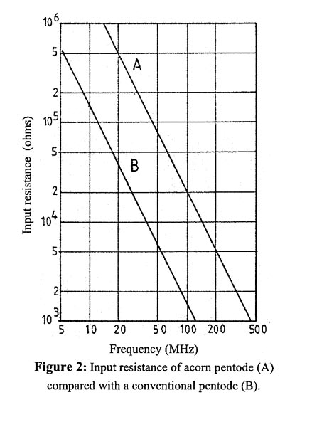
Figure two shows how the input resistance of a valve is affected by transit time, where a comparison is made between an acorn pentode and an equivalent, conventional pentode. At 30 MHz, the conventional pentode (B) has an input resistance of 17 k Ohms, which falls to only 1.5 k Ohms at 100 MHz. The equivalent figures for the acorn pentode (A) are 220 k Ohms at 30 MHz and 20 k Ohms at 100 MHz. This fall of input resistance, which has a critical effect on the amplification that the valve can provide is inversely proportional to the square of the frequency: if the frequency is doubled, the resistance falls by a factor of four and a ten-fold increase in frequency results in a hundred-fold decrease of input resistance. It is not difficult to see, therefore, that conventional valves were unsuitable for operation in the UHF band, whereas the acorn or similar miniature valves were better suited.
British companies such as MOV and Mullard found the acorn valves very difficult to manufacture because of the highly skilled labour required. As a result, considerable quantities of the valves were imported from the US for use in military radar equipment during World War 2. Because of the manufacturing problems and the eventual availability of alternative valves, the acorn valves were blacklisted by the Inter-Service Technical Valve Committee in June 1941.
With the commencement of high definition television in 1936 there was a need for a new type of valve capable of providing wideband RF amplification. The frequencies required for the Alexandra Palace transmission were 41.5 MHz for the sound channel and 45 MHz for the vision channel, the latter requiring a bandwidth of 3 MHz in order to accommodate the full picture information. In order to achieve satisfactory amplification of the video signal, valves were required with a high value of mutual conductance, and if this amplification was to be achieved at RF the valves must have low values of internal capacitance and self-inductance, in addition to a short electron transit time. The early valves produced for this role were far from satisfactory.
By the mid-1930s top-secret work was in progress at Bawdsey Manor in Essex on radio direction finding (RDF) - later to be re-named radar. For this, once again, valves capable of providing wideband UHF amplification were required. At this time Tom Goldup, a senior director of the Mullard Valve Company, was liaising with the British government and was made aware of this requirement. Mullard was wholly owned by the Dutch Philips Company and all the valve R&D work was carried out at the Philips Eindoven plant. Goldup approached Philips asking if there was a valve with the required specification. (Because RDF could not be mentioned I suspect he referred to television applications.) He was told that a suitable valve was being developed for the Dutch government; samples, therefore, could not be supplied to Mullard. It would appear that the UK government approached the Dutch government and samples were then supplied.
The valve in question was the EF50, which became available for television use in 1939. At this time all the valves were being manufactured in Holland.
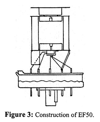
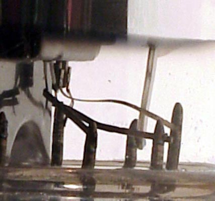
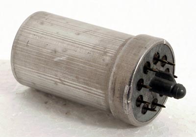
The construction of the Mullard EF50 is of interest because it marked a significant departure from the conventional types used in Britain at the time (see Figure 3). The usual Bakelite base and internal glass pinch were replaced by an all-glass base.
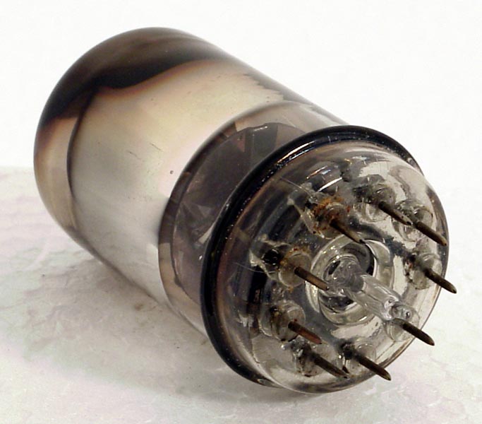
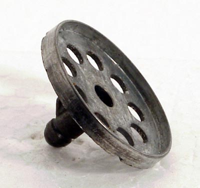
Elimination of the stem and pinch resulted in a considerable reduction in length of the internal wires. The valve had nine chromium-iron pins, which were sealed into the glass base and arranged uniformly around a central metallic spigot, which was keyed in order to facilitate insertion into the valveholder.
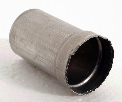
The spigot was joined to an external metal screen that covered the whole base, with small holes to allow the pins through. Because of the screening provided, it was possible to bring all the connections out to the base, avoiding the need for a top cap connection.
With the outbreak of war it was realized that the supply of EF50 valves would dry up and Mullard did not have the capability of manufacturing the special glass base with sealed-in pins. Consequently, just before Germany invaded Holland, a truck came from Holland with one million of these glass bases. Later, huge numbers of the valves were manufactured by Sylvania in the US.
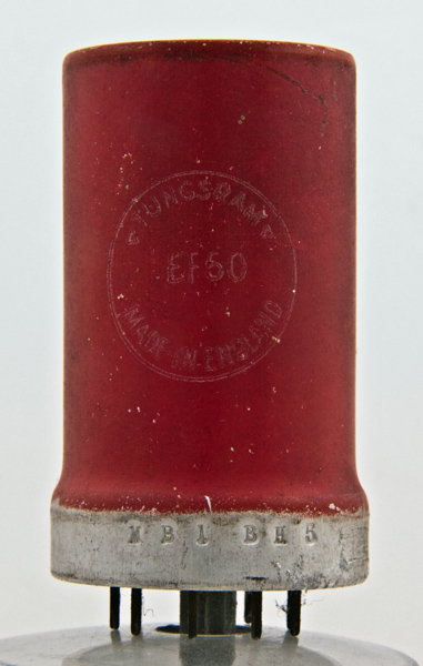
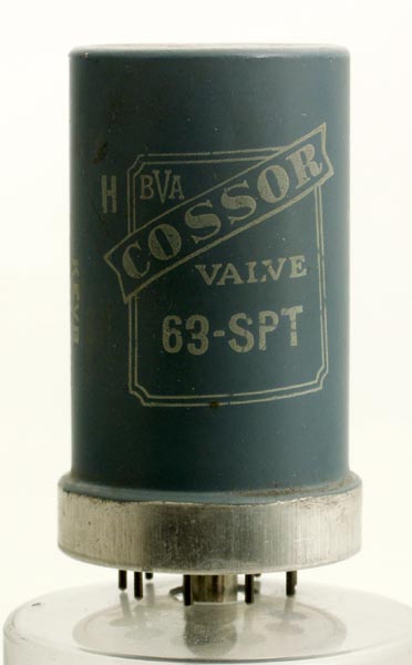
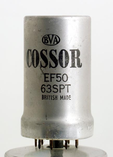
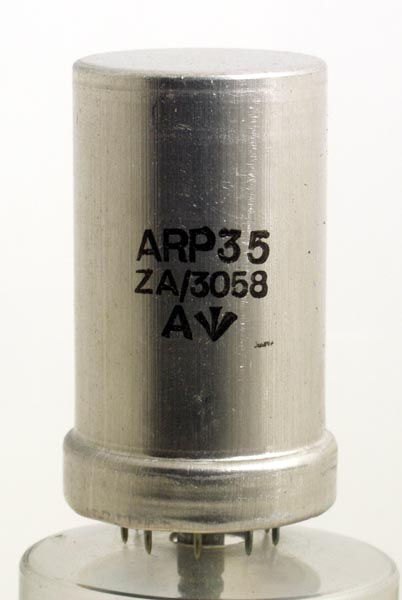
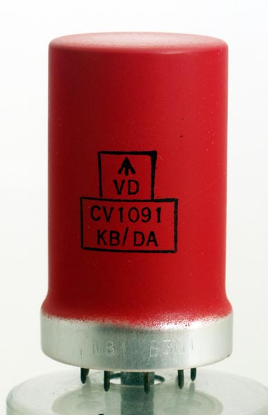
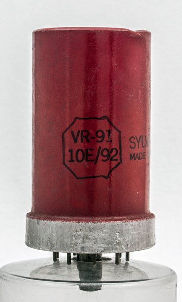
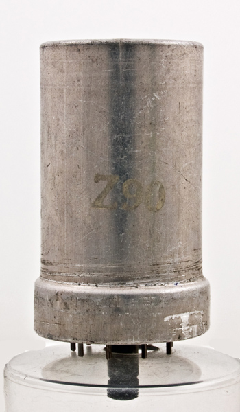
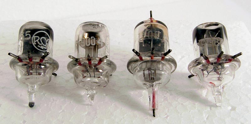
Fig. 4 A selection of EF50 valves in the museum
Figure 4 shows a selection of EF50 valves from various suppliers available during the War. The original Air Force type number was VR91, the Army type ARP35 and after 1941 the common valve designation of CV1091.
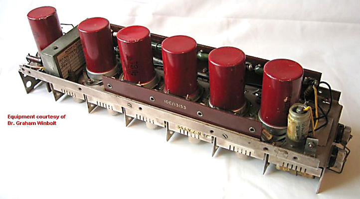
A typical use of the EF50 was in the Pye 45 MHz IF strip - Receiving Unit Type 153 - which was used universally in British radar equipment during the war. A picture of this can be seen above. It had six EF50s (VR91s) and one EA50 (VR92) miniature signal diode.
A variant of the EF50 was the RL7 (VRI36). This had aligned grids to reduce partition noise, and the cathode was connected by leads to four separate pins to reduce still further the self-inductance. The valve was capable of proving RF amplification at 200 MHz and could thus displace the acorn valve. In post war years it was re-designated as EF54.
I am grateful to Dr Graham Winbolt who provided the photograph of the Receiving Unit Type 153 (Pye IF strip).
The information on the RL 7 was obtained from Brian Callick's excellent book Metres to Microwaves (Published by Peter Perigrinus Ltd. and obtainable from the IEE).
For more information of early British valves see Thrower, K (1992) History of the British Radio Valve to 1940 1004
R J Sutherland comments that the Russian 4Zh1L/12Zh1L VHF pentode on a Loctal base (B8B) looks similar to the EF50/EF54 and wonders if the internal structures are also similar. The 4Zh1L/12Zh1L is often thought to be based on the German (Telefunken) RD12Pb or more possibly the RV12P2000 but the construction is not the same and is more correctly compared with the RV12P2000. In any event the Russians would have had free access to the EF50 family during the war.